TSF◇ for distal tibial fractures
Badri Narayan, FRCS; Liverpool University Hospitals, UK
The views and opinions expressed in this section are those of the surgeon.

Treatment with TSF can be a suitable strategy for:
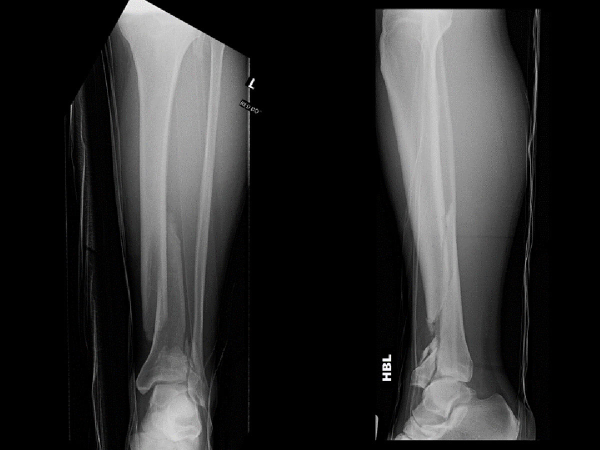
- AO/OTA 43A and 43C fractures complicated by severe soft tissue injury, including acute compartment syndrome (Figure 1)
- AO/OTA 43A and 43C fractures with tenuous skin
- Patient preference for ring fixation
Procedure
The limb is prepared and draped above the level of the knee, ensuring that the patella is visible.
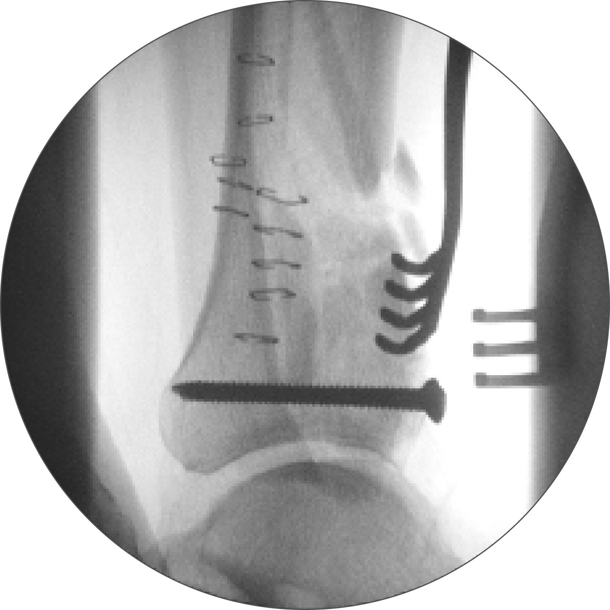
A tourniquet is used only for the reduction of the articular surface in fractures where anatomical reduction and screw fixation of displaced articular fragments is indicated. Such screw fixation, if indicated, is first performed, and the skin incision(s) closed
(Figure 2). The tourniquet is now deflated and can be removed.
External fixation
A distal reference configuration is chosen. Rings of appropriate size are slid over the leg (one or two for the proximal fragment, and one for the distal fragment).
The leg is placed either on an elevated radiolucent block, or on plastic supports, so as to facilitate intraoperative screening.
Distal Ring
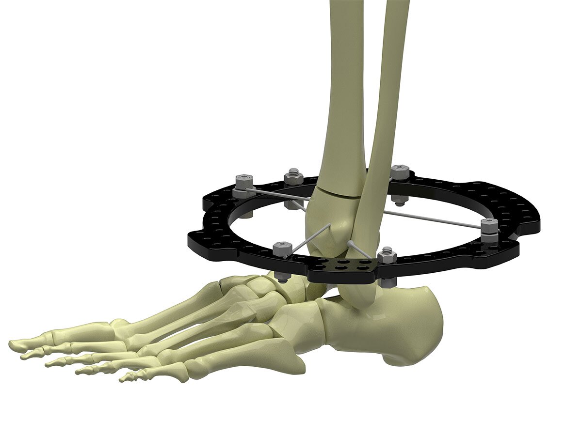
A transverse Olive Wire is inserted from lateral to medial in the distal fragment, ensuring that this wire is superior to the synovial reflection of the ankle. As a rule of thumb, a transverse wire placed at the level of the epiphyseal scar of the tibia is safe.
While rotation of the Ring can be adjusted in the program, it is simpler to achieve this intra-operatively.
Two short Threaded Rods can be run superiorly off the centre of the Master Tab, and the Ring rotated until these are nearly superimposed on the AP view. Bolts holding Half Rings can also be used similarly.
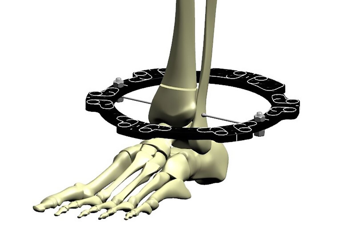
The Ring is now fixed superior to this wire using Wire Fixation Bolts, making sure that wire fixation holes (for Struts 1, 2, 3 and 6) are avoided. The Wire Fixation Bolt on the near side of the olive is tightened to avoid the Ring sliding on the wire, thus achieving referencing in the AP plane (Figure 3a).
The image intensifier is now switched to the lateral view, and the Ring is visualised. It is tilted so as to be perpendicular to the posterior cortex of the distal tibial fragment. If visualising this is difficult, the articular surface of the lower tibia is chosen, and the Ring is tilted forward relative to this (anterior distal, posterior proximal) by about 10 degrees.
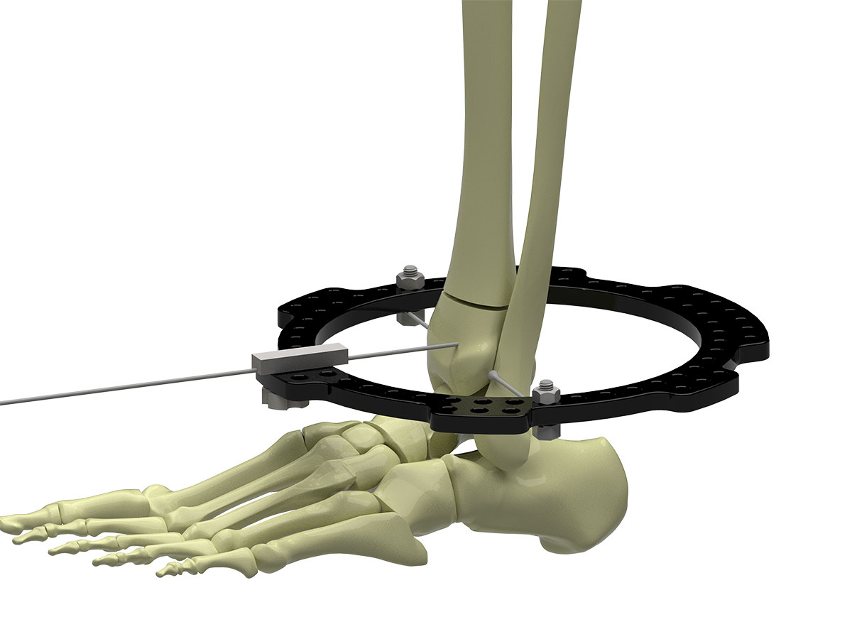
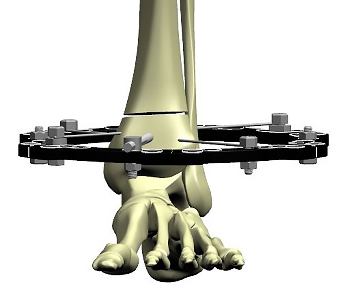
A temporary positioning wire can be placed to set the tilt of the Ring in the sagittal plane. The Wire Guide (102930) or Wire Fixation Bolt is placed on the Ring directly over the anterior cortex. A Smooth Wire is drilled through this in an anteroposterior direction, reaching but not exiting the posterior cortex. This holds the Ring perpendicular to the tibia in the sagittal plane, thus making sure the Ring is orthogonal to the distal fragment (Figure 3b).
A medial face wire is now driven in the distal fragment proximal to the Ring. The Wire Guide can be used to ensure that this wire remains flush with the Ring. The position of the Ring is confirmed on the Lateral view, and both wires are tensioned. The AP positioning wire can now be removed
(Figure 3c).
A third retrofibular wire can be passed above the Ring; this crosses the medial face wire at a very good crossing angle.
The distal tibia provides two safe zones for half pins – anterior to posterior (AP) lateral to the Tibialis Anterior, or medial to lateral (ML) from the bare area of the tibia. Fracture configuration and soft tissue injury will dictate whether the use of such half pins is possible.
An AP half pin can be safely inserted at this stage if indicated (Figure 3d). If an ML half pin is used, one must ensure it does not come in the way of Struts 1 and 6 (left tibia) or Struts 2 and 3 (right tibia), and, if in doubt, this pin can be inserted after the struts are attached to the two Rings.
Proximal Ring block
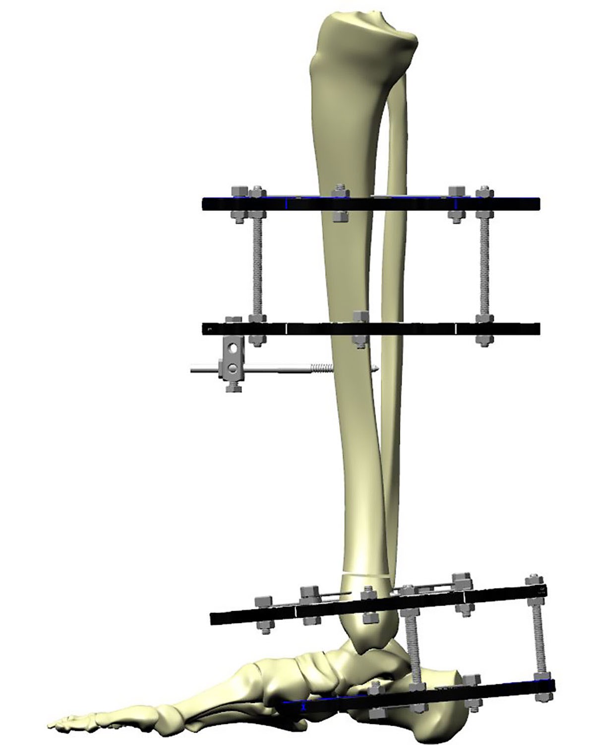
The proximal Ring block is constructed and attached using standard technique (Figure 4a).
Typically, a distance of about 7 to 8 finger-breadths between the Rings on either side of the fracture allows the use of the FAST FX◇ or SMART FX Short and Medium Struts, permitting a stable frame and,
at the same time, minimising Strut changes (Figure 4b).
Additional stability
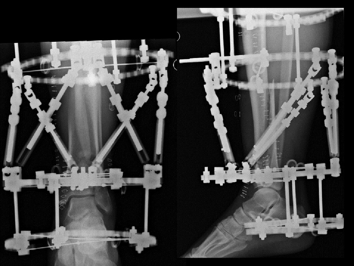
A single Ring with three wires, or three wires and a half pin may not provide enough stability for weight bearing, particularly in large individuals. Fracture configuration may also not permit this number of fixation points. In such cases, an extension to the foot allows greater security of distal fixation (Figure 5). If used, this part of the construct can be removed at about six to eight weeks.
Reduction and correction
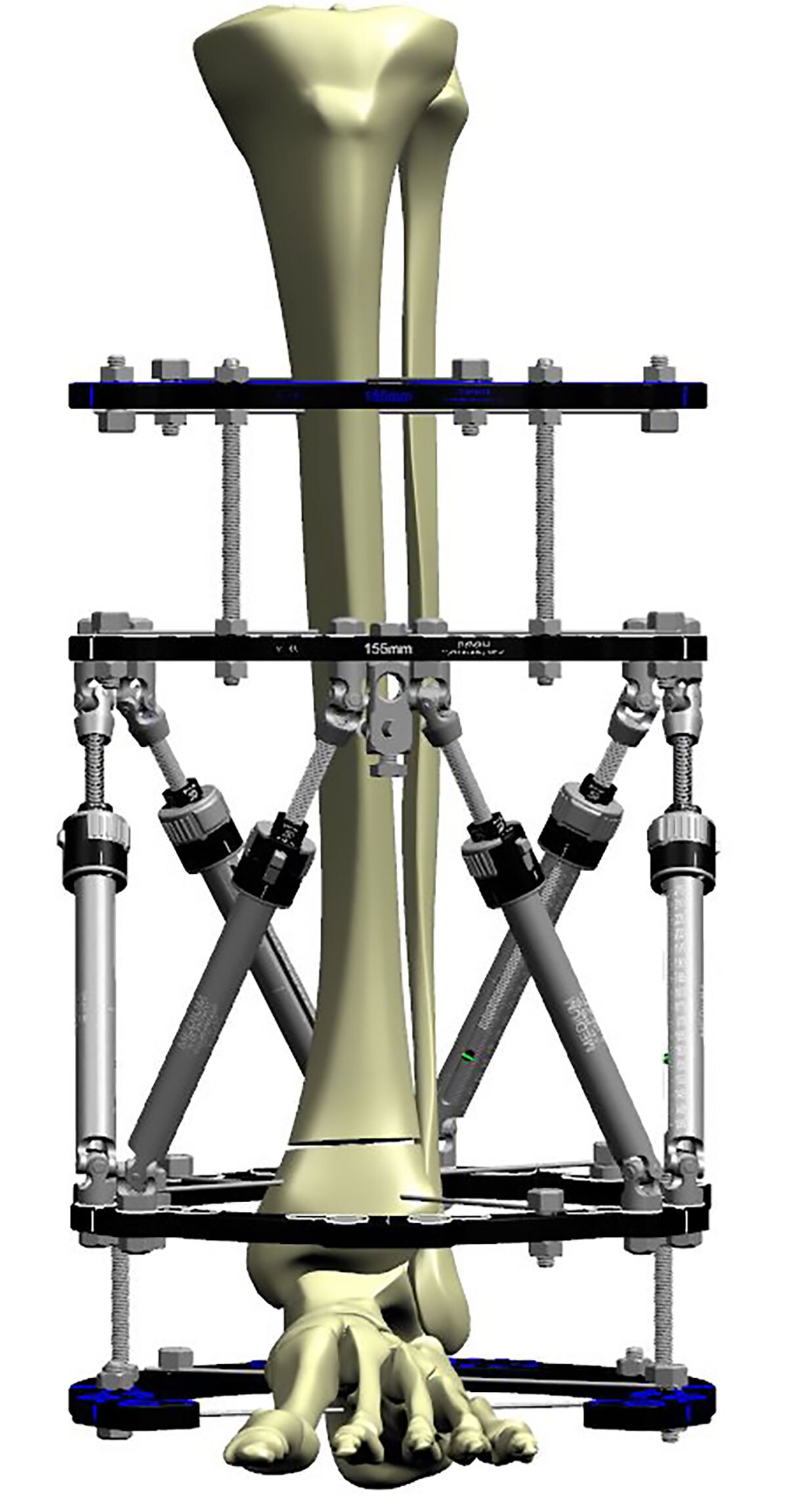
The use of SMART FX or FAST FX◇ Struts allow a provisional reduction in the operating Theatre. SMART FX Struts are locked by removing the Acute Adjustment Bands.
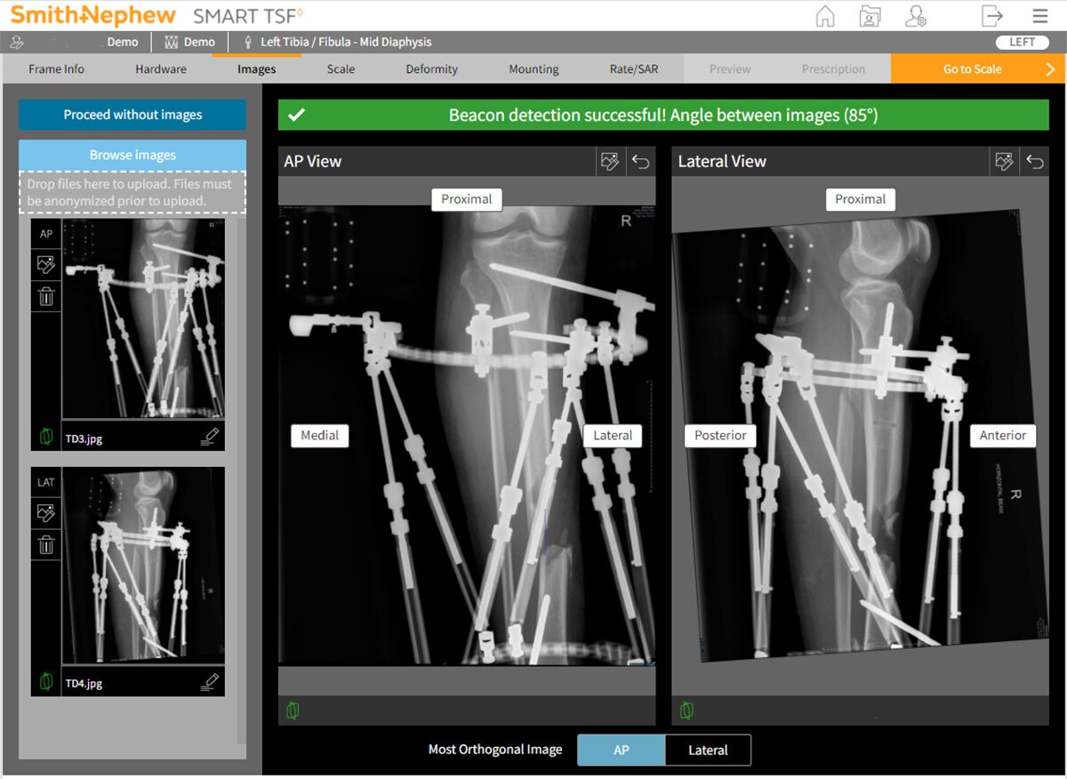
AP and lateral radiographs can be captured in Theatre or on the following day post-op. X-ray images should focus on the fracture and include the Beacon where used. At least one of the AP or Lateral images should be a true orthogonal image of the anatomy. The Ring does not need to be visualized orthogonally (Figure 6).
Progression of healing
Fractures of the distal tibia typically heal in about 16-20 weeks. Refer to commentary about CT scans, page 33. Dynamization or reverse-dynamization may enhance fracture healing, and can be employed at the surgeon’s discretion.
Soft tissue strategies
The gold standard for soft tissue loss over the medial tibia is a local plastic surgical flap. In situations where a flap cannot be performed, a TSF◇ can be used with “intentional deformation” of the fracture while approximating the skin. For example, a case with anteromedial soft tissue loss with a distal tibial fracture is held with a TSF applied with fracture “mal-reduced” in varus and recurvatum. The skin ends can now be brought together, and the skin sutured. The fracture is gradually brought into alignment after a latency period of four to six weeks.
The Direct Scheduler tool in SMART TSF◇ software facilitates input of initial and final Strut settings, with no need for deformity analysis or Mounting Parameters. It will generate a schedule to get from initial to final settings, at a pace defined by soft tissue healing (Figure 7).
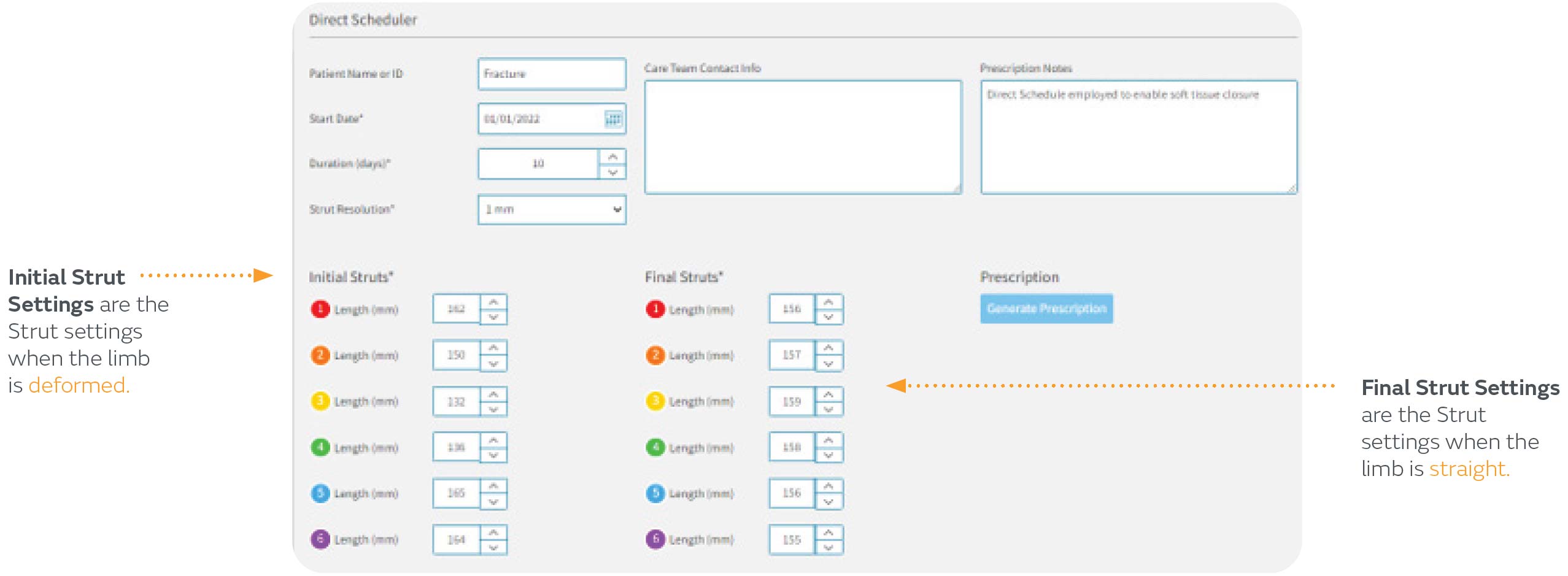
Direct Scheduler can be found in the Resources section of SMART-TSF.com
Suggested Videos