Managing hypertrophic nonunions with TSF◇
Nando Ferreira, PhD; Stellenbosch University, Cape Town, SA
The views and opinions expressed in this section are those of the surgeon.
Introduction
Hypertrophic tibial nonunions are ideally suitable for management with TSF circular fixation because of the fixator’s ability to affect closed distraction and accurate deformity correction while simultaneously providing stable fixation to allow early functional rehabilitation.
When one appreciates that excessive strain is the root cause of hypertrophic nonunions, reducing the strain across the nonunion site would conceivably allow for bone formation and union. The mechanobiological explanation for how closed distraction promotes healing in stiff nonunions is two-fold; firstly, the use of a mechanically competent external fixator, like the TSF, reduces excessive parasitic interfragmentary motion while a small amount of distraction increases the interfragmentary distance. The end result of this approach is decreased strain to within tolerable limits for bone formation.1
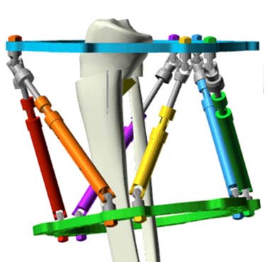
TSF construct
A standard two-Ring TSF construct is applied with each Ring firmly affixed to the respective bone segment in the classic Rings First method. The proximal and distal Rings are then connected with TSF Struts with a resultant frame that mimics the fracture deformity. Depending on the deformity severity, Ring sizes and spacing should be considered to prevent acute Struts-to-Ring connection angles and resultant conformational instability.2
Proximal fixation consists of one tensioned wire and two hydroxyapatite (HA) coated half pins. The medial pin is placed on an Angled Pin Connector which allows a long pin to be placed and ensures rigid fixation of the proximal Ring to the proximal bone segment. A Ring block with two tensioned wires and two HA Coated Half Pins ensures fixation over a large area for distal fixation. A fibula osteotomy is performed, most commonly in the distal third of the fibula.
Case example
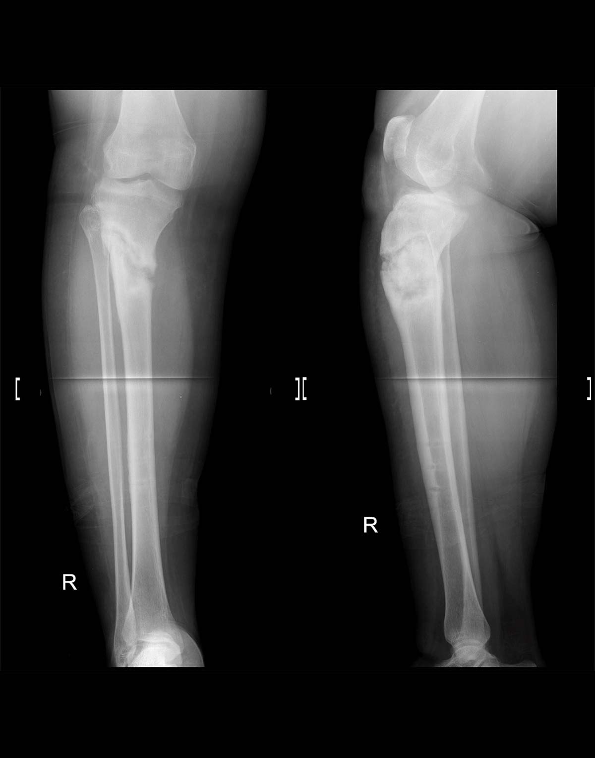
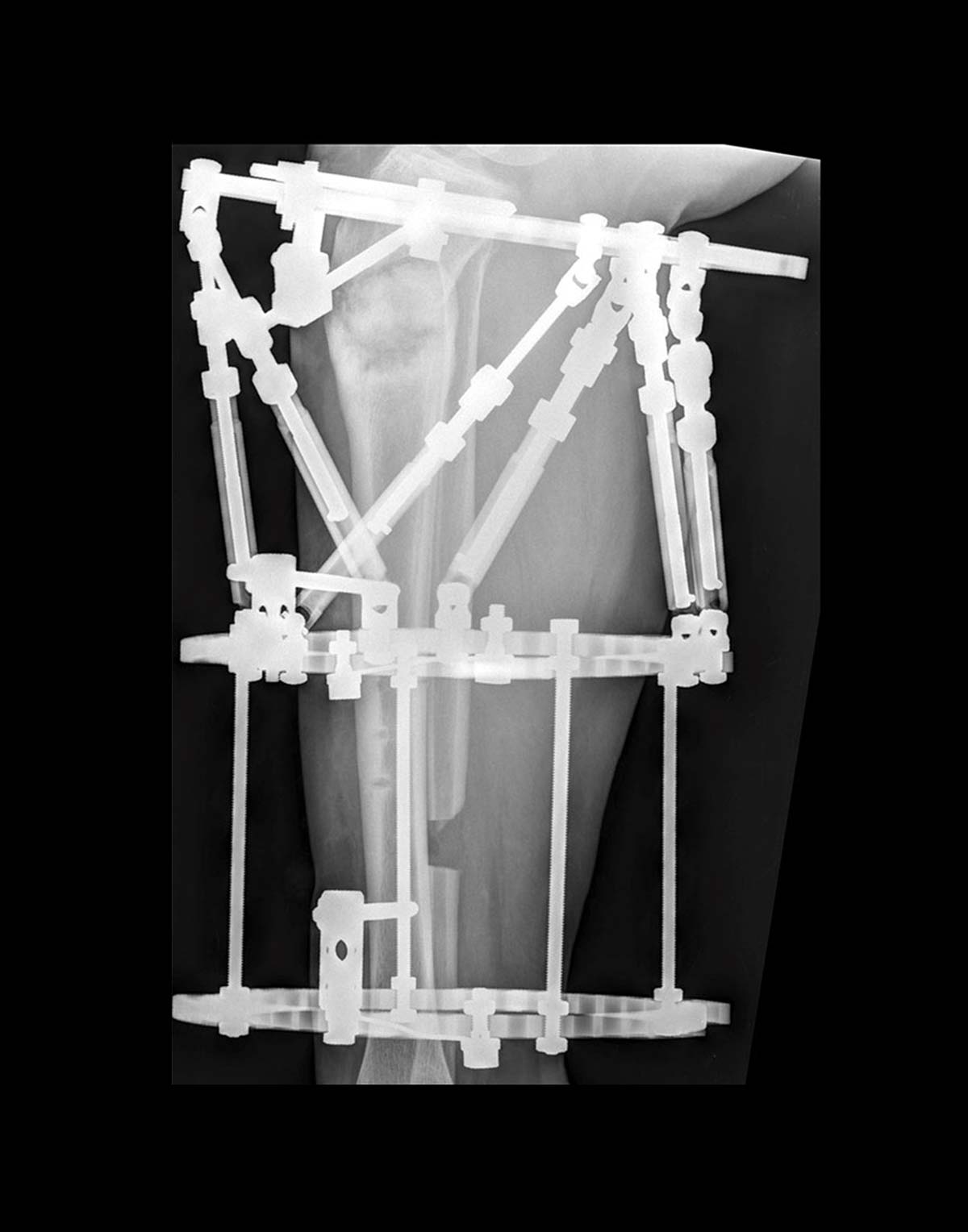
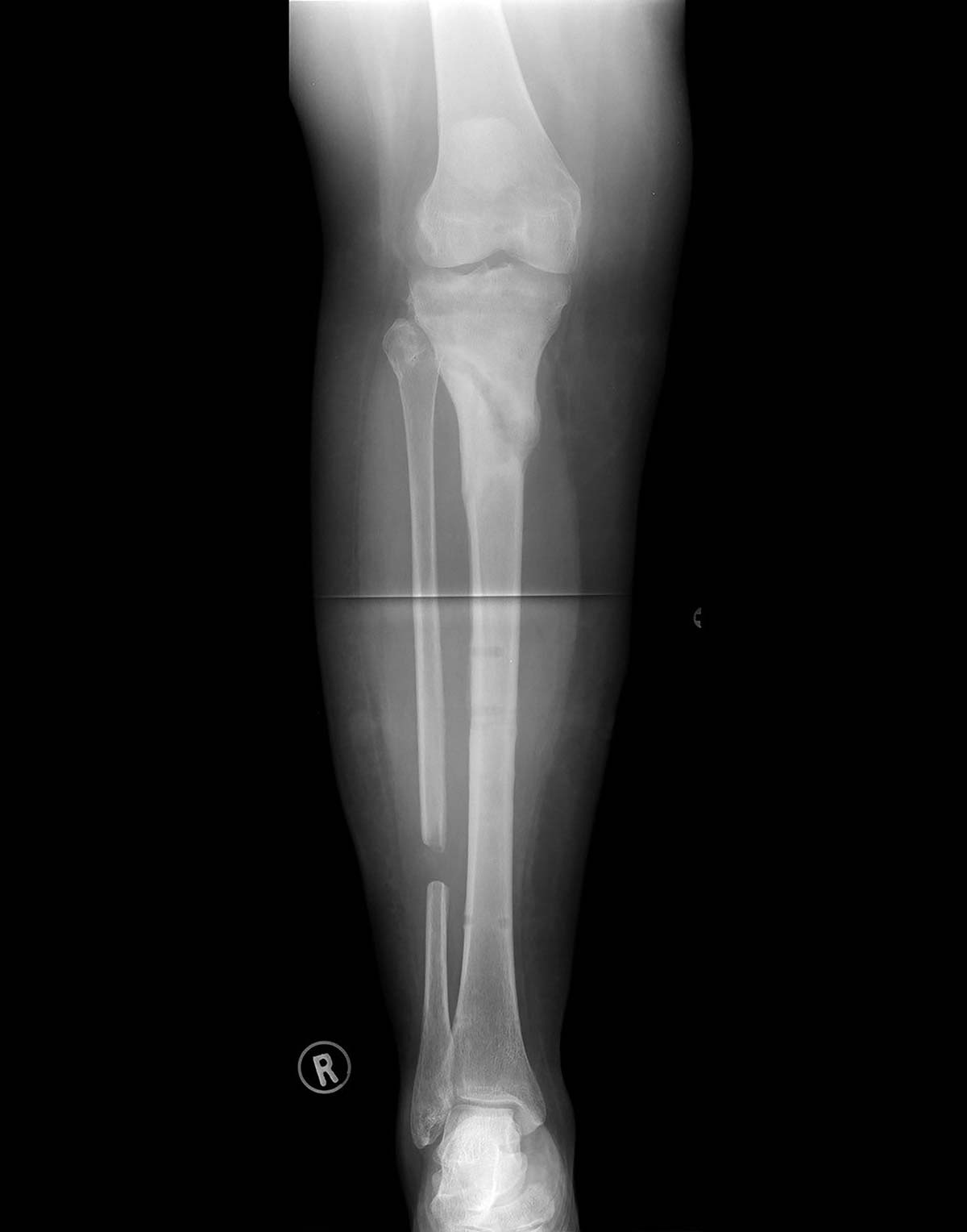
A 34-year-old-female who sustained an open fracture of her right proximal tibia was treated by open reduction and internal fixation with proximal tibial locking plate. She complicated with fracture related infection and fixation failure for which she underwent debridement, removal of the locking plate and systemic antibiotic therapy. At presentation to the reconstruction unit the patient had a stiff, varus collapsed hypertrophic nonunion of the right proximal tibia and was clear of infection (Figure 1a). Application of a TSF was performed (Figure 1b) and union achieved (Figure 1c).
Safe zones and pin insertion
It is important to note that any strategy to reduce pin site complications starts in theatre. The longevity of any external fixator is dependent on bone-pin interface surviving the duration of treatment. Pins are routinely added to traditional tensioned wires to ensure rigid Ring-to-bone segment fixation so that every frame movement is accurately translated to bone segment movement. The use of Angled Pin Connectors allows pin placement that is oblique relative to the Ring which allows better purchase in short peri-articular bone segments.
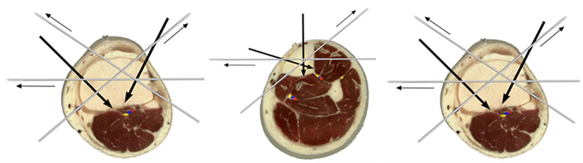
Unaltered figures from Nayagam et al. Safe corridors in external fixation: the lower leg (tibia, fibula, hindfoot and forefoot). Strateg Trauma Limb Reconstr. 2007;2(2-3):105-110.3
A thorough anatomical knowledge is paramount for safe pin and wire placement to avoid iatrogenic damage to vital structures like nerves, vessels and tendons. It is advisable to consult wire placement atlases or published articles that describe safe zones/corridors when applying these devices.4 It is generally accepted that transverse wires, antero-lateral to postero-medial “face” wires and antero-medial half-pins can safely be placed along the entire length of the tibia (Figure 2).
Osteotomy options
Osteotomy through the nonunion site is generally not advisable. Even deformities that appear very stiff on examination are generally easily correctable with gradual TSF correction. A fibula osteotomy might be required and is performed where most convenient, unless an associated fibula deformity is present; in this case a fibula osteotomy at the level of the fibula deformity is advised.
Software planning
At the conclusion of the surgical procedure, all clinical parameters required to plan the correction are documented on the TSF◇ Worksheet. Alternatively, they can be entered directly into the software using the Intra-Op feature on any mobile device. These inputs include the sizes of the Rings used, Struts used and their settings, rotatory frame offset and the axial rotational deformity measurement. These measurements, along with the radiographic analysis findings will be needed to plan the deformity correction schedule.
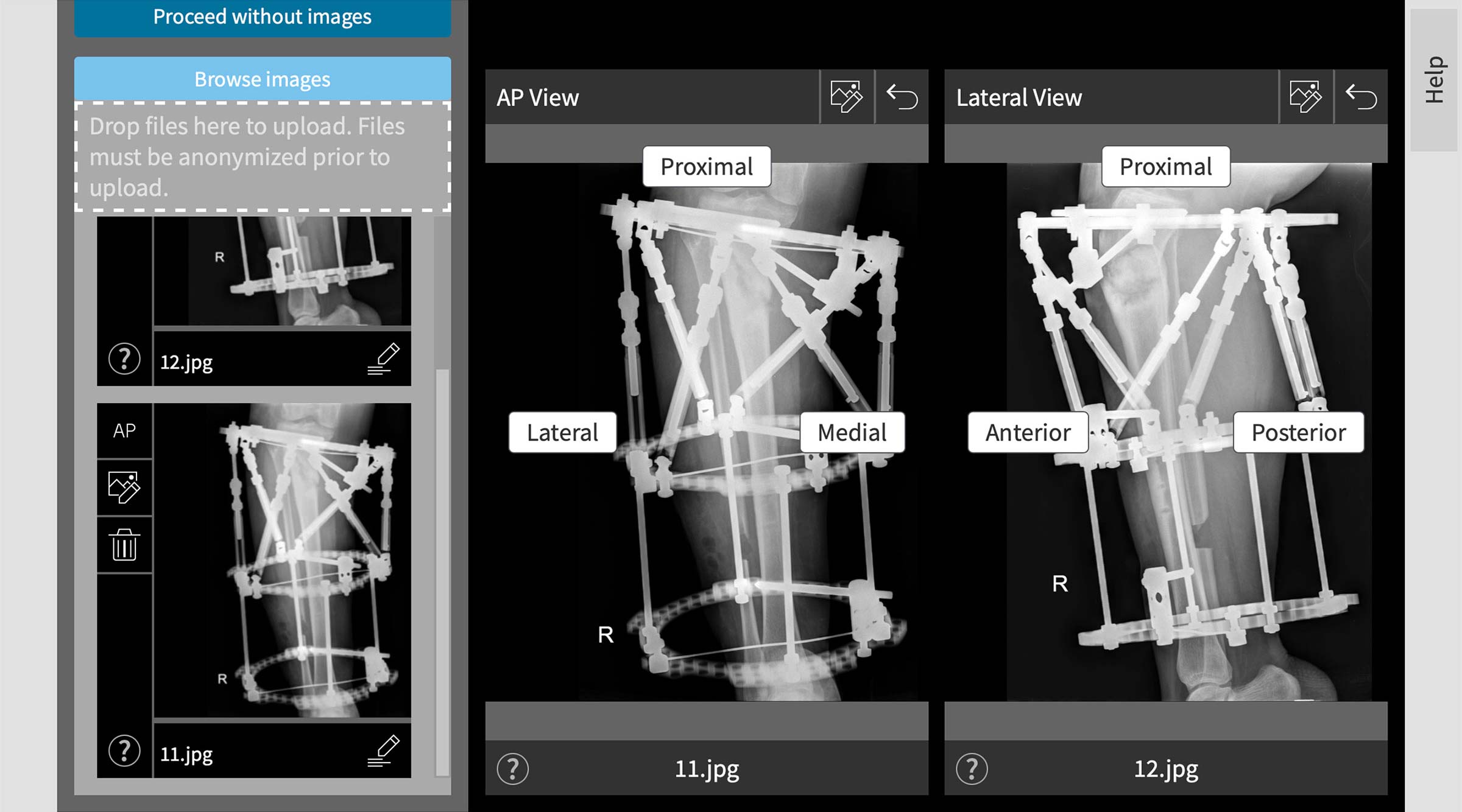
Imaging and diagnostics
Accurate post-operative X-rays are vital to accurate planning and subsequent correction. The X-ray images can then be uploaded onto the SMART TSF platform in-suite deformity analysis and correction planning (Figure 3).
The most important considerations when taking post-operative X-rays are:
- The two views should be perpendicular to each other.
- Either the AP or Lateral X-ray image should be orthogonal to the bone and the most orthogonal view selected in the software.
- The Origin and Corresponding Point, including segmental axes and the the SMART TSF Beacon if used, should be visible on the X-rays.
- Although not absolutely necessary, it is advisable to be able to see the entire reference Ring on both views.
- You should add a size marker to calculate image magnification. The Beacon will accomplish this, as well as calibrate the image for subsequent measurements.
Software planning strategies
The reference Ring is generally chosen as the Ring closest to the area of interest – the nonunion site in this case. This allows mounting and deformity parameter measurements with the least amount of parallax error.
Following the Rings First method of frame application, the Total Residual mode (crooked frame on crooked bone) is usually preferred for analysis and correction planning. In this software mode, correction could potentially end with a slightly crooked frame but anatomically aligned bone.
Following analysis, the true three-dimensional deformity should be accurately represented in the software. Use these images to compare with your post-operative X-rays prior to commencing any correction. Pay specific attention to the relationship between the Rings and their respective bone segments. If the in-suite graphic representations are not similar, go and look for mistakes during
data entry (Figure 4a and 4b).

Common places where mistakes are made include:
- Selecting the incorrect-sided (left versus right) limb
- Inadvertently clicking varus instead of valgus, anterior versus posterior, etc.
- Images loaded on the SMART TSF◇ software being incorrectly orientated – anterior/posterior error of the lateral radiograph is most frequent
- Incorrect strut measurements captured or entered
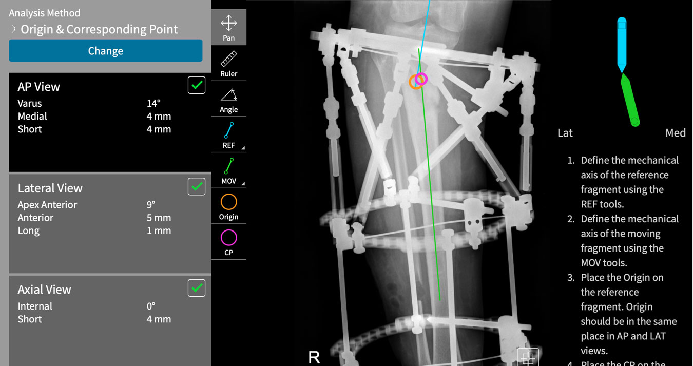
Software methods
Closed distraction of hypertrophic tibial nonunions are ideally suited for the Apex = Corresponding Point method of deformity planning (Origin and Corresponding point analysis method on the SMART TSF◇ software) (Figure 5). This planning method allows the physician to predetermine the amount of length to be added to the correction and uses the apex of deformity as the hinge point, which eliminates the need to measure or enter any translational parameters. One does then only have to calculate angular deformities, mount the reference Ring relative to the apex of the deformity and decide on the amount of additional length required. This can simplify radiological analysis considerably.
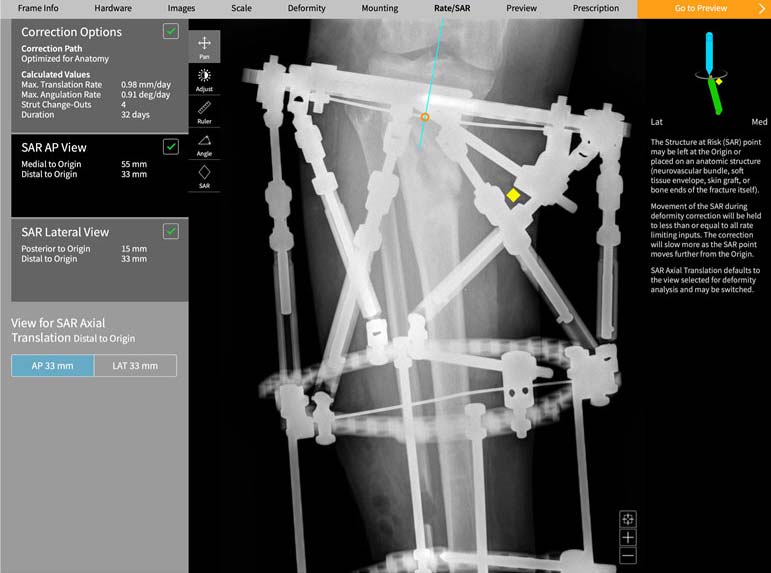
Structure at risk
Nonunions frequently complicate high-energy trauma fractures. As such, soft tissue flaps or scarred tissue might be present around the nonunion site. What happens with these soft tissues during distraction and deformity correction should be considered when programming the rate of correction. Here the Structure at Risk (SAR) function in the SMART TSF◇ software allows the physician to control the rate of distraction of any area of concern (Figure 6). It is prudent to limit the rate of lengthening at this zone – 2mm per day in this case example.
Post-correction considerations
As no osteotomy is performed through the nonunion site, no mandatory latency period is required, and correction can commence as soon as a correction schedule is calculated.
Any frame stable enough to effect correction and distraction will undoubtedly be stable enough to allow early weight bearing and functional rehabilitation. Early active range of motion of adjacent joints and weight bearing as tolerated is advised. Emphasis on proprioceptive retraining and normalization of gait pattern is key during the initial post-operative period.
References
- Tanwar Y, Ferreira N. Monofocal distraction of stiff hypertrophic nonunions. How and why does it work? A Systematic review and mechanobiological explanation. J Limb Lengthening Reconstr. 2019;5(2):54. doi:10.4103/jllr.jllr_19_19
- Henderson ER, Feldman DS, Lusk C, van Bosse HJ, Sala D, Kummer FJ. Conformational Instability of the Taylor Spatial Frame. J Pediatr Orthop. 2008;28(4):471-477. doi:10.1097/BPO.0b013e318173ecb1.
- (Figure 2) – Nayagam S. Safe corridors in external fixation: the lower leg (tibia, fibula, hindfoot and forefoot). Strateg Trauma Limb Reconstr. 2007;2(2-3):105-110. doi:10.1007/s11751-007-0023-7.
- Atlas for the Insertion of Transosseous Wires and Half-Pins – the Ilizarov Method. Smith+Nephew Inc 2003.
Suggested Videos