TSF◇ for proximal tibial fractures
Richard Gellman, MD; San Joaquin General Hospital, CA
The views and opinions expressed in this section are those of the surgeon.

Introduction
The TAYLOR SPATIAL FRAME◊ (TSF) is an excellent device to treat complex challenges in the proximal tibia. Due to the abundance of excellent periarticular plating systems available to surgeons in North America and Europe, the use of ring fixation is generally reserved for more select cases.
- Infected nonunions and/or malunions of the tibial plateau or proximal tibia, with or without bone loss
- Extra articular AO type A tibial plateau fractures with soft tissue challenges, the decision to select a method that allows immediate full weight bearing
- Segmental tibia fracture patterns
- Type B1 or C1 tibial plateau fractures can be reduced and stabilized with small fragment screw fixation followed by frame application or with the use of wire fixation alone.
- Fractures below a total knee replacement where there is sufficient “real estate” for pin and wire fixation around the tibial stem
- Certain pediatric fractures where flexible nailing techniques would not provide sufficient stability
- Patients with a complex soft tissue injury where the use of a TSF will allow bony union to be achieved without the need for free flap reconstruction

Technique
Success in using TSF◇ Ring fixation in the proximal tibia requires careful preoperative planning of wire and half pin placement. Surgeons accustomed to using the TSF with a standard transverse smooth wire to establish coronal plane alignment and then adding three multiplanar half pins in a “one method fits all” approach to fixation in the proximal tibia will need to expand their horizons. Bone “tunnels,” or defects from previous screws used for internal fixation, or fractures that extend into the plateau may prohibit insertion of commonly used transverse wires.
It is critical to carefully align the single proximal Ring parallel to the knee joint in the coronal plane and within 5 degrees in the sagittal plane to ensure accurate visualization of radiographs for deformity correction (Figure 1).
Wire fixation must be carefully planned. The goal is to stabilize any simple fracture, often with opposing Olive Wires. Wire fixation is placed proximal, distal or at an angle to avoid poor fixation in areas of internal fixation screw tracks. Five points of fixation for the single proximal Ring is ideal. This can be an all-wire construct or any combination of wires and half pins depending on fracture or deformity configuration.
Wire and half pin fixation should be placed no closer than 1cm from the internal fixation or knee replacement components to lessen risk of infection.

There is controversy regarding the placement of wire fixation within the anatomic recesses of the knee joint capsule. Whenever possible, it is advisable to keep fixation about 1-1.5 cm distal to the joint. However, in cases of very proximal fractures or bone loss near the joint, it may be necessary to place wire fixation just below the articular plateau. In these patients, vigilant pin care and removal of infected wires will be necessary to prevent septic arthritis (Figure 2).

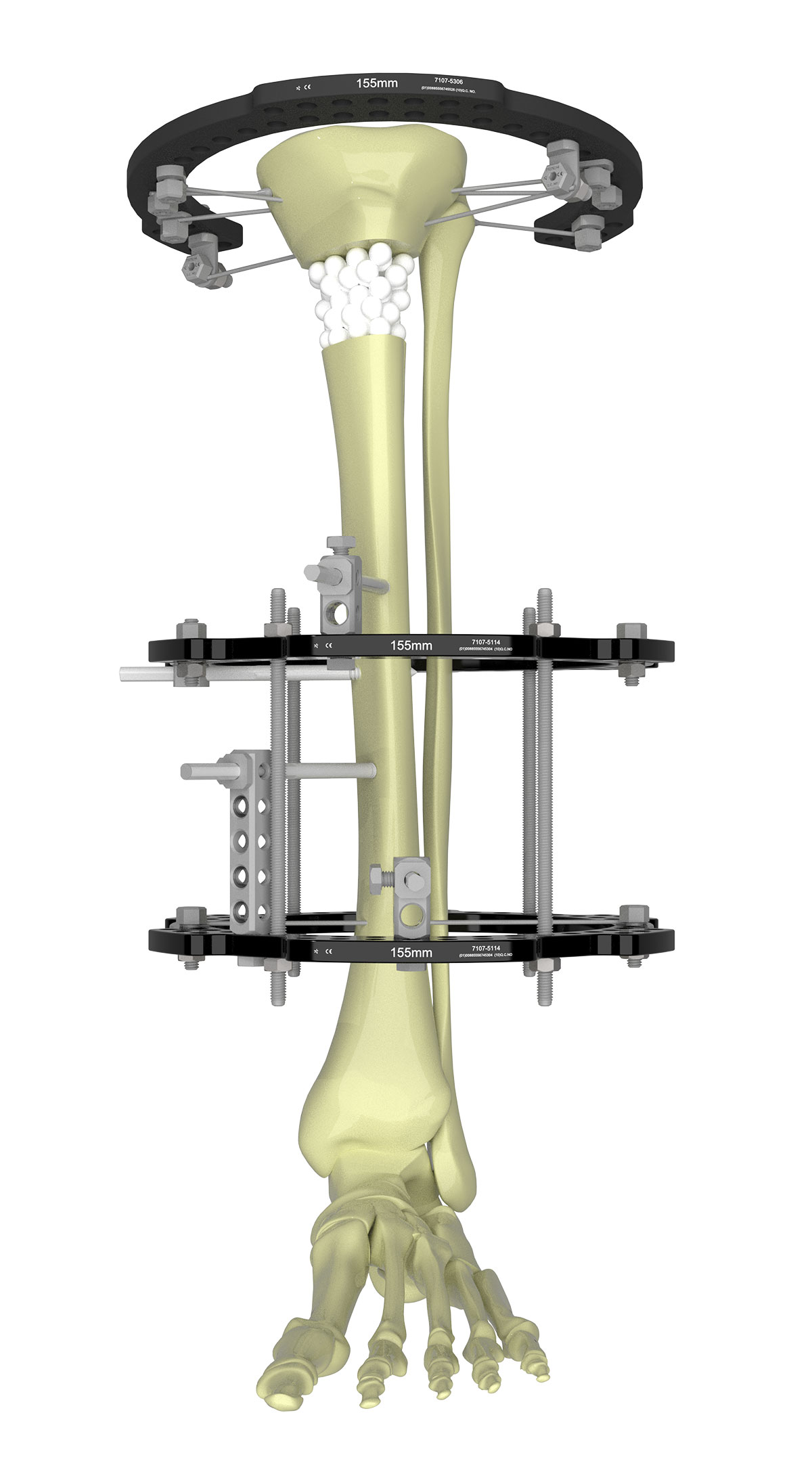
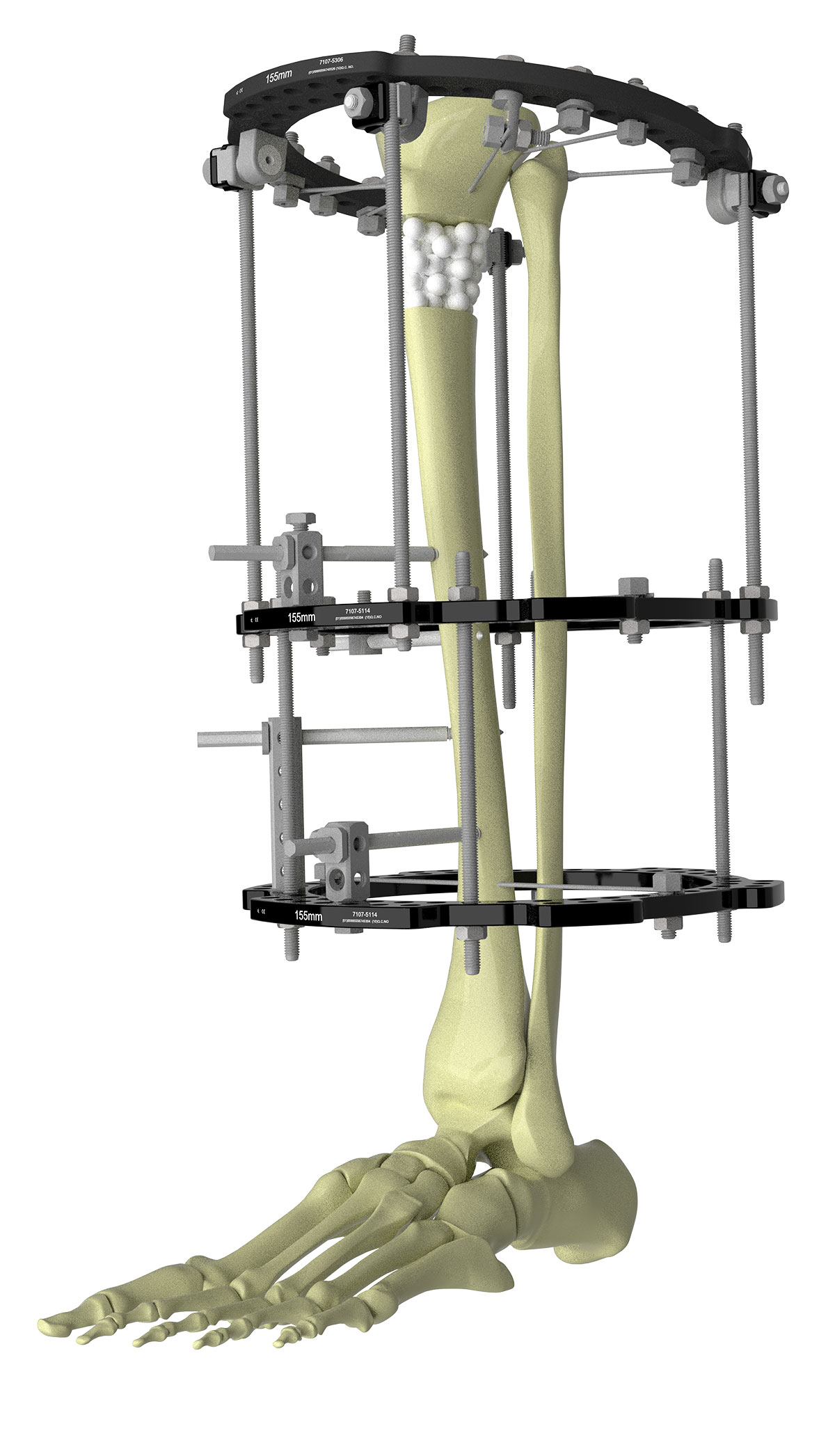
In general, Ring fixation in the mid-tibia is achieved with a Ring block assembled with 150mm Threaded Rods and secured initially with a transverse Smooth Wire above the proximal Ring to establish the coronal plane alignment followed by a sagittal plane half pin on the distal Ring to set the sagittal plane alignment.
Three more half pins are added to create a strong construct that will allow for removal of the transverse wire in the clinic if it becomes infected or symptomatic during treatment.
Alternatively, some frame mechanic studies have shown that one Ring with multiplanar angled half pin configurations can provide similar stability as the two-Ring construct described above (Figure 3).
I typically use a single distal Ring only in lighter patients or pediatric patients that have rapid healing times.
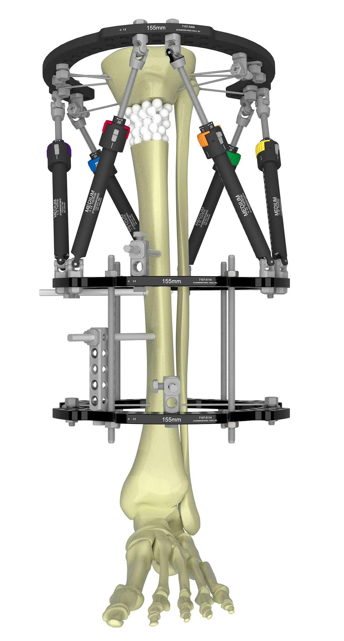
Strut selection is dependent on the clinical problem. In general, I use FAST FX◊ or SMART FX struts for acute fractures or lax nonunions where I can apply axial traction following frame application to obtain an initial closed reduction with ease (Figure 4). For malunions or stiff nonunions, I prefer Standard Struts.
Case Example
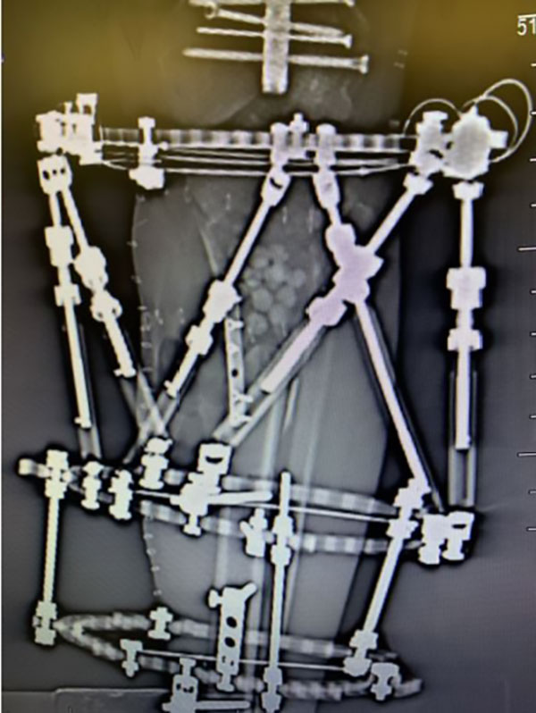
A straight EVOS◇ MINI plate provides structural support to the defect filled with graft.
Software strategies
Which deformity analysis strategy chosen in SMART TSF◇ software is at the discretion of the surgeon and their level of comfort with each method. In theory, any method will work for any fracture or deformity. TraumaDots lends itself to a fracture configuration where two bone fragments need to be re-aligned. In a fracture with bone loss, SuperDot provides an easier means to define the hinge point for correction.

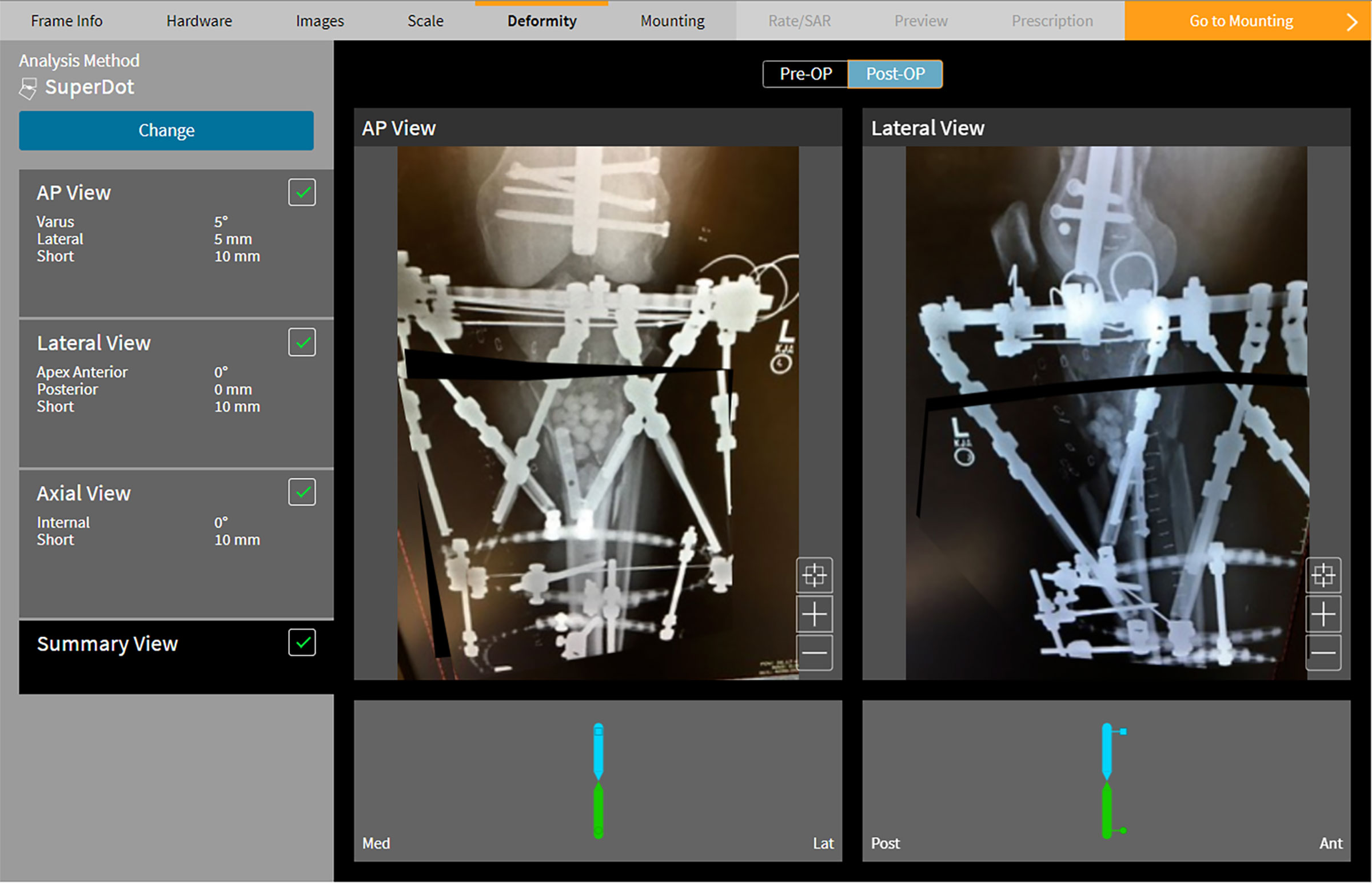
In the above example the distal fragment is traced out to include the area of bone loss (Figure 6a). The SuperDot is placed on the fracture line. The software generates a prescription to drive regeneration from the fracture site (Figure 6b).
Fracture healing
Depending on the indication for a TSF◇, one of the greatest challenges is how to best assess fracture union or maturation of regenerate bone following distraction osteogenesis. Formation of 3 of 4 cortices on plain radiographs is the standard for defects of the tibial shaft, whereas assessment of bone density and filling in of fracture defects is necessary in metaphyseal bone (Figure 7).
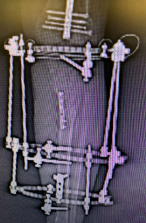
Once there are radiographic signs of healing, Struts can be replaced with Threaded Rods, adding conical washers or Conversion Clamps to maintain the exact Ring position. This allows better visualization around the fracture and distraction sites (Figure 8).
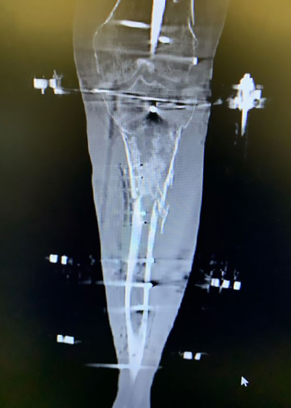
CT scans are commonly used to provide the most accurate assessment of fracture healing prior to frame removal (Figure 9).
