TSF◇ in the management of open tibial fractures
B. J Ollivere, MBBS, FRCS, MD; University of Nottingham, UK
The views and opinions expressed in this section are those of the surgeon.
Introduction
The spatial frame remains the gold standard for management of open tibial fractures (Gustillo Grade II+). In a review of 111 tibial fractures treated with TSF (55 open, 56 closed) at a Level One Trauma Centre between 2009 and 2020, union was shown to be 93.5% and average time in frame was 27.9 weeks.1 This compares to 74% success in a fix and flap approach,2 and 92% in nail-plate techniques.3 Patients with complex soft tissue injuries that are not open should also be considered for Ring fixation (Figure 1a).
Like all external fixation constructs the Ring fixator should be constructed to allow for the fracture pattern and likely future treatment requirements:
- Is “dialed in deformity” needed for soft tissue management (Figure 1b)
- Will soft tissue reconstruction be needed and therefore access for microvascular flaps (Figure 1c)
- Will secondary bone transport be required needing a suitable Ring construct (ie Ring blocks).
In addition, when faced with a complex open fracture, there are considerations for fixation:
- Long working lengths do not control angular deformity well and Ring blocks may be required.
- All fixation should be outside of the zone of injury and the zone of subsequent surgery.
- Patients will typically be wearing their Rings for upwards of 6 months and as such non-bridging weight-bearing constructs are to be preferred.
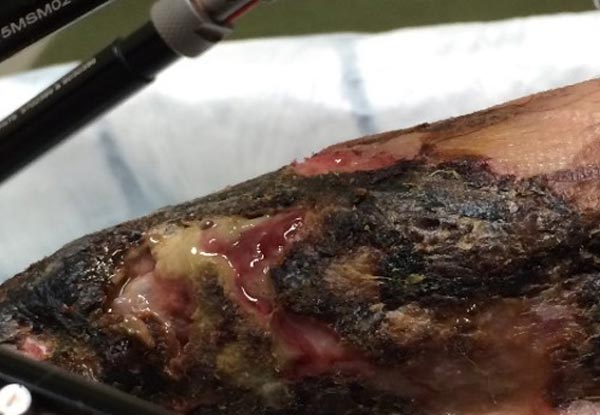
Challenging soft tissue
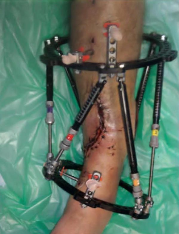
Bony deformity to close soft tissue
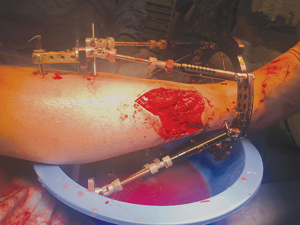
Rotary frame offset used to leave a window over the wound
Spatial corrections in trauma
When planning fixation it is also important to consider the correction power of the Rings and planning for any likely corrections. The angle of the Struts and the working length of the hexapod are intimately related:
- Lower-angled Struts provide better length corrections.
- Lower angles provide stronger translations.
- 45 degree-angled Struts provide optimal rotational corrections.
The working length can be adjusted using Ring blocks (Figure 2a) or angled pin connectors and drop wires (Figure 2b), and the same fracture can be effectively treated with constructs that provide optimal corrective power.
A further consideration when undertaking spatial corrections in trauma is the fibula. In all but the most unusual circumstances, the fibula will also be fractured. Undertaking corrections without holding the fibula at the ankle at the syndesmosis risks altering the ankle geometry. It is therefore recommended to transfix the fibula and tibia with at least one Olive Wire.
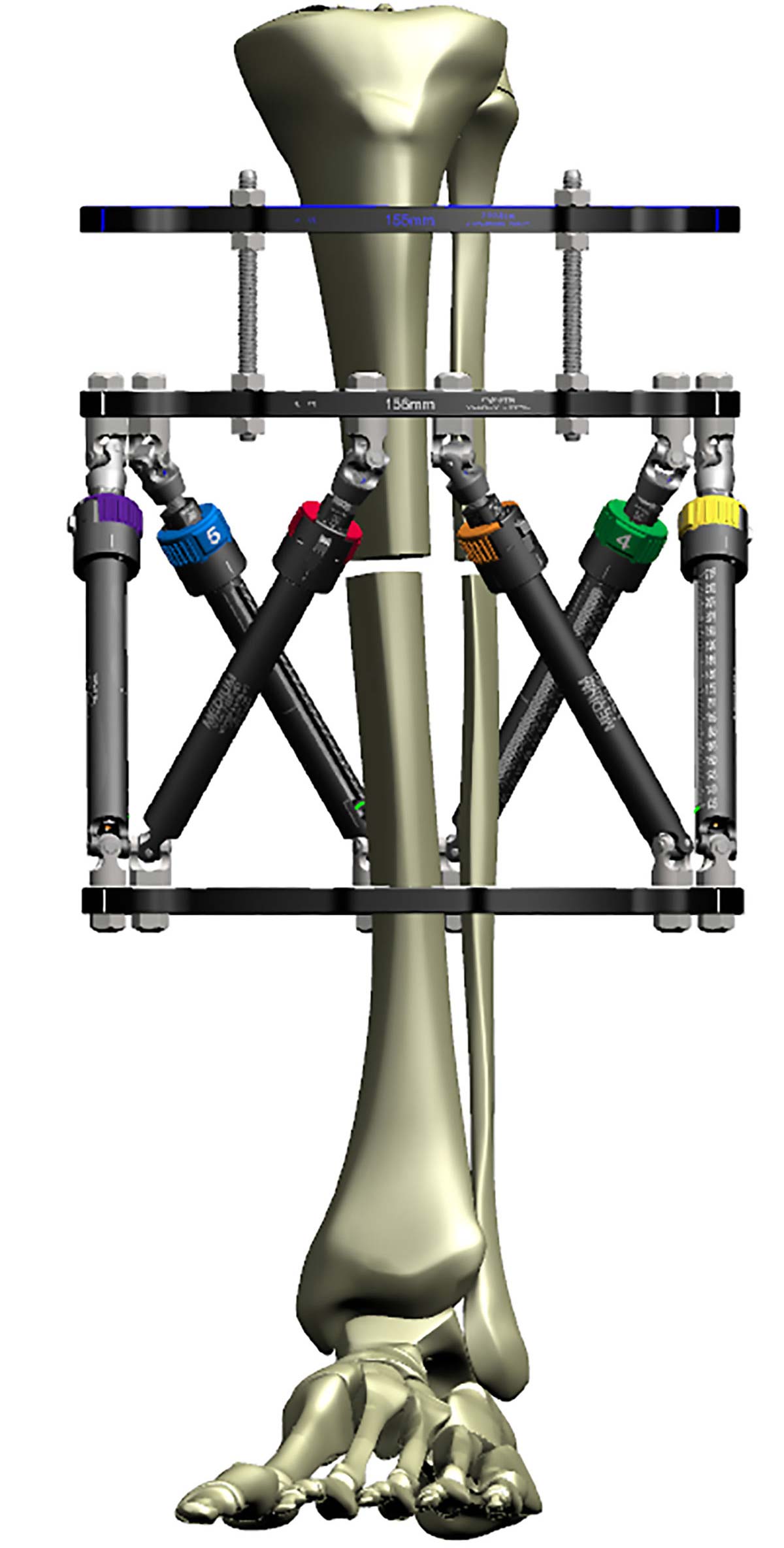
Construct optimized for rotational correction
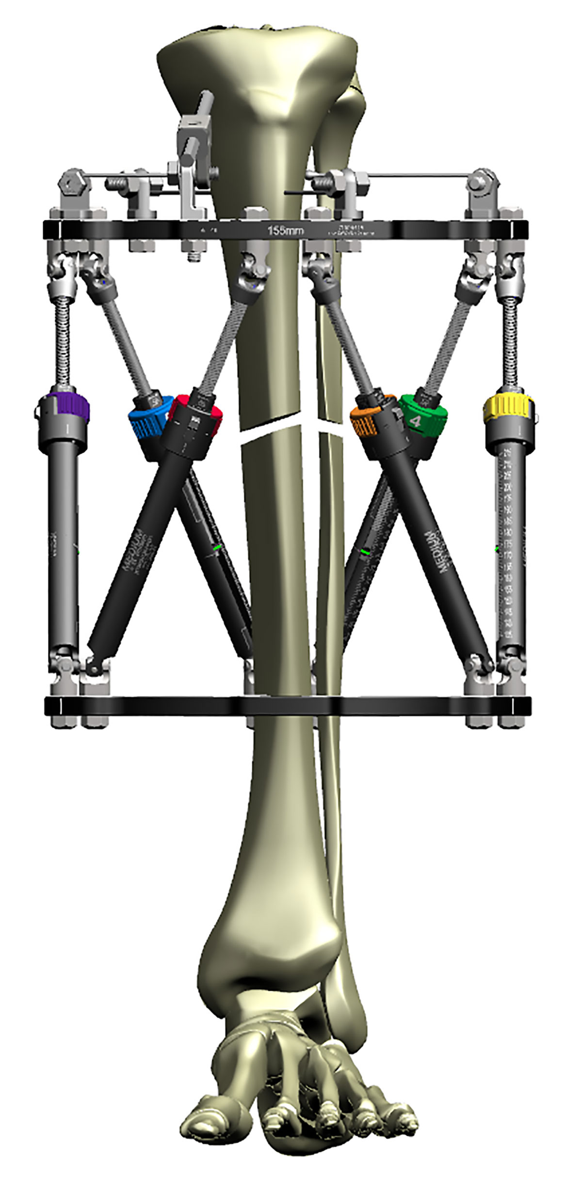
Construct optimized for AXIAL correction
Segmental fractures
While stacked Rings work well for segmental fractures, the intermediate Ring must have two points of fixation to the intermediate segment or correction will not occur correctly (Figure 3a).
In the case where the soft tissues do not allow for two points of fixation then a single half pin may be used so long as the apex of the half pin is at 90º to the correction plane. Single points of fixation do not withstand rotational forces and ideally should not be used.
Stacked frames should also not be considered for bone transport. The construct is not biomechanically sound and does not provide 1mm of axial translation reliably. The variation in Strut angles as the floating Ring traverses, results in poor regenerate formation at best or failure of transport at worst.
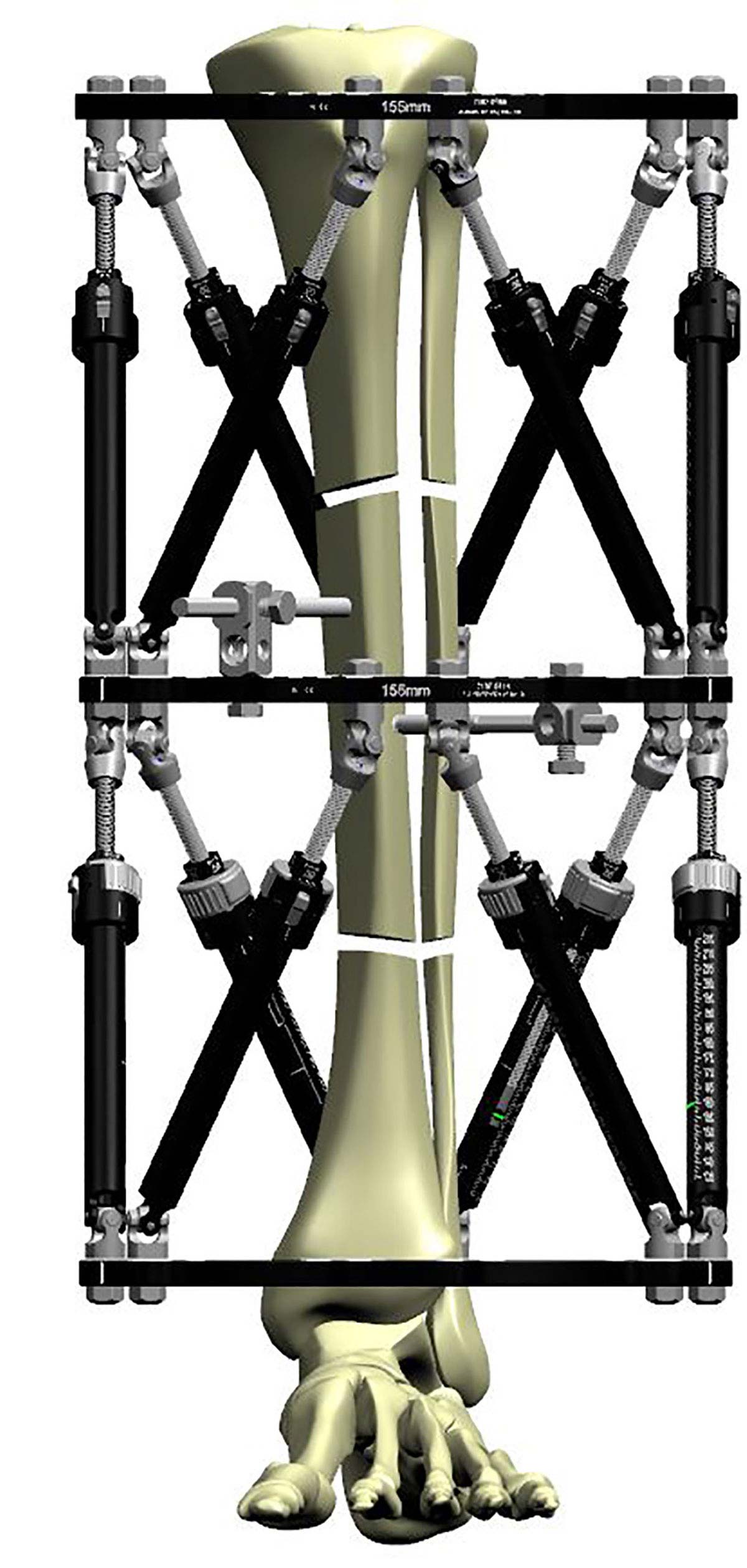
Segmental fractures fixed with a stacked frame
Case Example
This segmental fracture was complicated by an acute compartment syndrome, and the fasciotomy complicated by slow healing. A circular frame was chosen for definitive treatment, and applied about 4 weeks post-injury.
The image shows a stacked TSF◇, fixed using the principles illustrated in “Fundamental Principles of Stable Frame Construction.” Software allowed fine-tuning of correction over five weeks to achieve contact and alignment. The stable construct supported the stimulation of full weight-bearing.
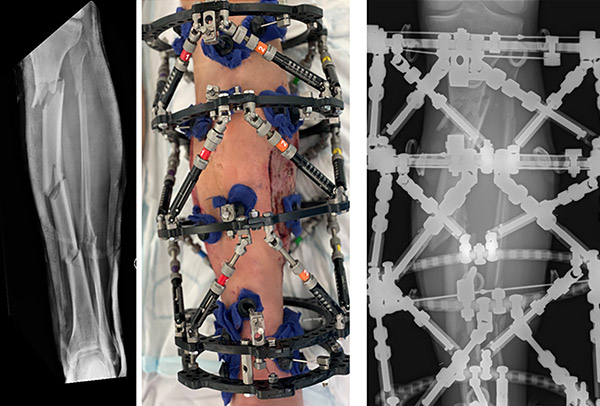
Note two points of fixation at ideally 90º to each other, on the intermediate Ring
Hardware options – Step-off plates
A standard two Ring TSF◇ construct is sufficient for the majority of fracture applications. When close to the knee, a 2/3 Ring can be utilised to allow for knee flexion.
Consideration should be given to the Ring sizes spacing and points of fixation to ensure optimal stability of the frame.
The proximal and distal Rings are then connected with TSF Struts with a resultant frame that is able to undertake a trauma correction as needed and does not suffer from instability. The SMART TSF◇ software provides the flexibility to utilise Step-Off Plates for patients who have soft tissue impingement issues (Neutral Step-Off, Figure 4a), to avoid Strut change outs (30mm Step-Off) or to undertake custom strut mounts (Figure 4b).
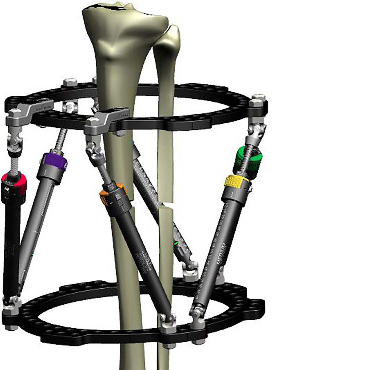
Neutral Step-off Plates allows a “window” over soft tissue
Top down view showing clearance of Struts from soft tissue
While these options provide flexibility, and the software will not allow a deformity correction on an “unstable” construct, it is important to remember that the “standard” hexapod configuration provides optimal stability.
30mm Step-Off Plate used to create space over wound
30mm Step-Off Plates on Struts 4 and 5 can be removed during correction
Hardware options – Dynamization
If Dynamization is likely to be employed at a later stage, it is helpful to incorporate the Dynamization Kit hardware at the time of primary surgery. Placing the Dynamization Washers on the back face of the most orthogonal Ring (Figure 5a) will leave the frame in a static position and allows it to be easily converted later without the need for additional hardware in clinic (Figure 5b).

Dynamization Washer above the Ring – not driving any axial micromotion

Dynamization Washer below the Ring – driving axial micromotion
Hardware options – Pin placement
Particularly in the case of open fractures, it is essential to optimise soft tissues and reduce the risk of soft tissue complications. Any strategy to reduce pin site complications starts in theatre and particularly when a known correction is taking place, a hybrid construct with half pins and fine wires is optimal to providing correction. The longevity of any external fixator is dependent on bone-pin interface surviving the duration of treatment and use of pins, in addition to traditional tensioned wires, will help ensure rigid Ring-to-bone segment fixation so that every frame movement is translated to bone segment movement.
Placement of half pins should provide a fixation angle of as close to 90º as possible, and the use of a steerage pin on the apex of the tension side of the deformity helps reduce soft tissue complications and maximise deformity correction power (Figure 6a).
Particularly in the peri-articular fixation segments the use of the short Angled Pin Connector helps to reduces the modulus mismatch, helps to reduce the risk of periprosthetic frame fracture and ultimately increases stability of the Ring, particularly against bending and torsional moments where fine wires do not provide optimal stability (Figures 6b and 6c).
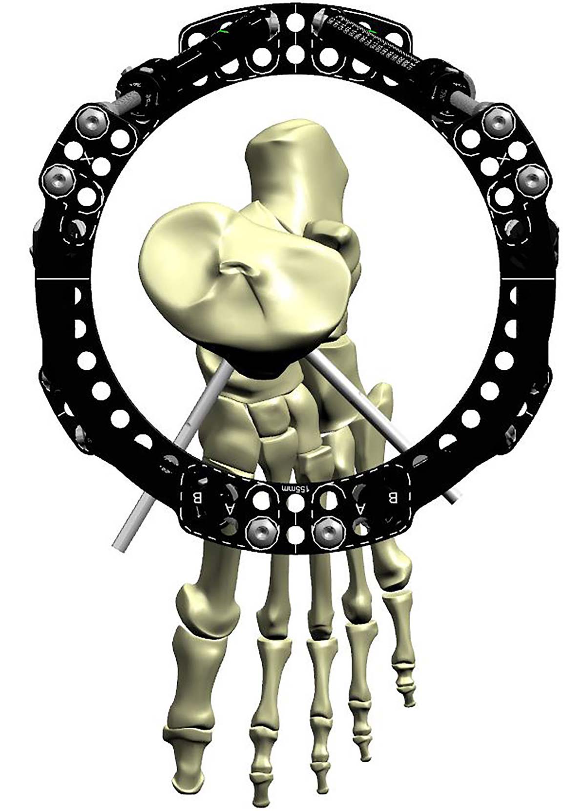
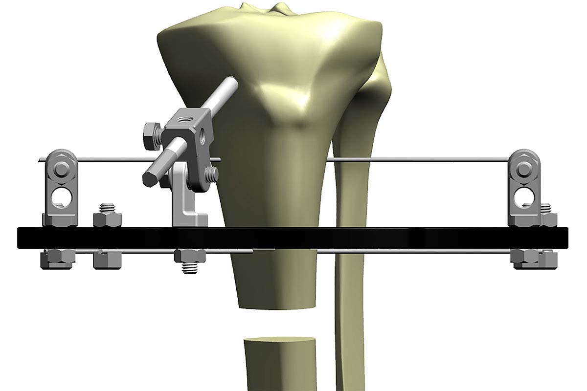
Proximal fixation optimized with angled pin connector to increase frame stability
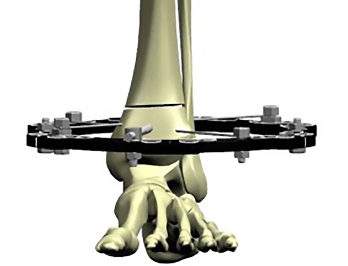
Use of a half pin in small distal segment fixation can avoid the need to bridge the ankle.
Hardware options – Custom Strut Mount
The frame construct can be used to optimise soft tissue reconstruction. At the most basic level the use of 2/3 Rings with two rotated 2/3 Rings can provide ample space for both free flap anastomosis and insertion (Figure 7a).
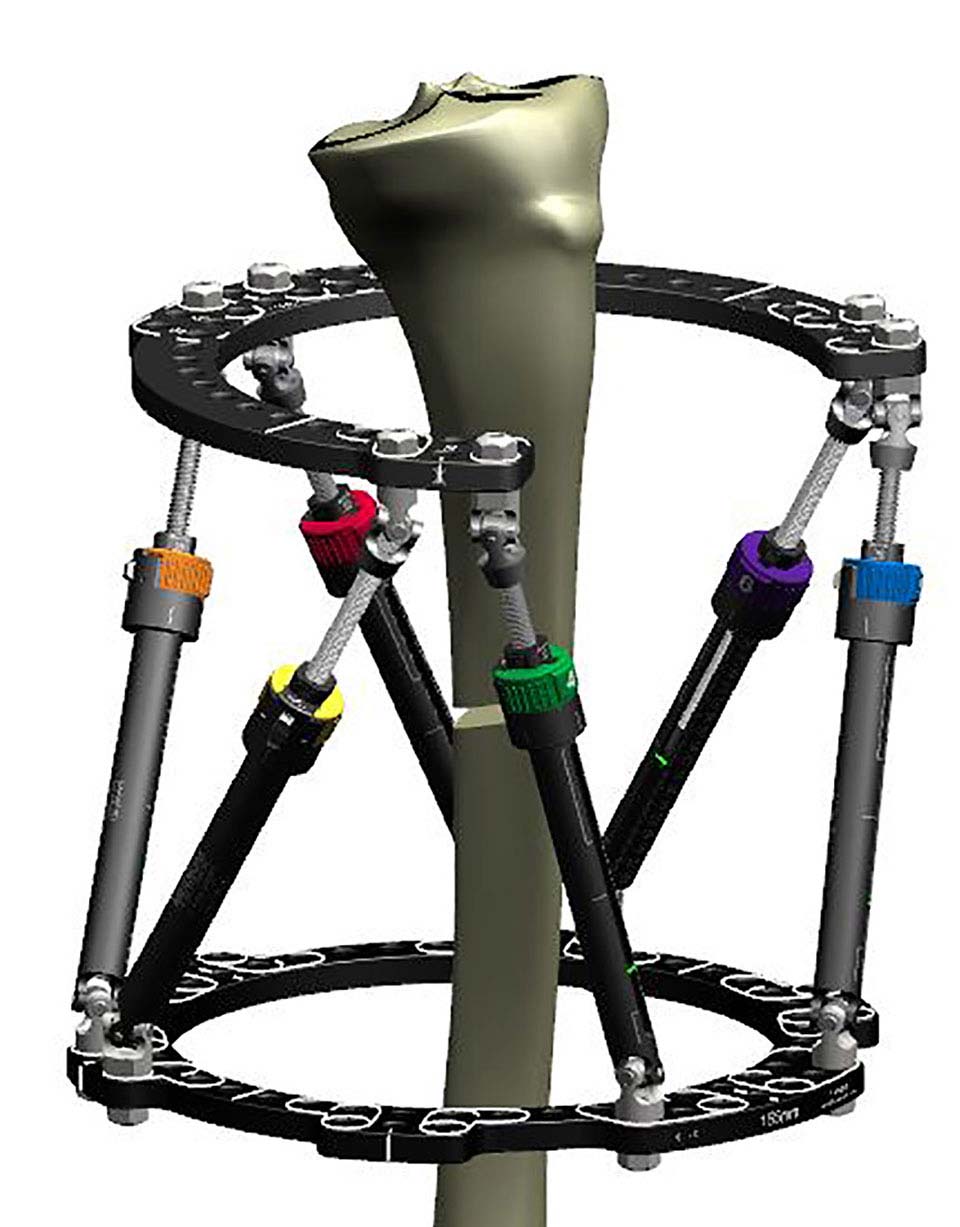
Proximal 2/3 Ring with 180º Rotary Offset combined with Custom Strut Mount on the Distal Ring to maximize the window over a wound
In some circumstances Custom Strut Mount can be used to allow for soft tissue swelling or to accommodate a free flap (Figure 7b and 7c).
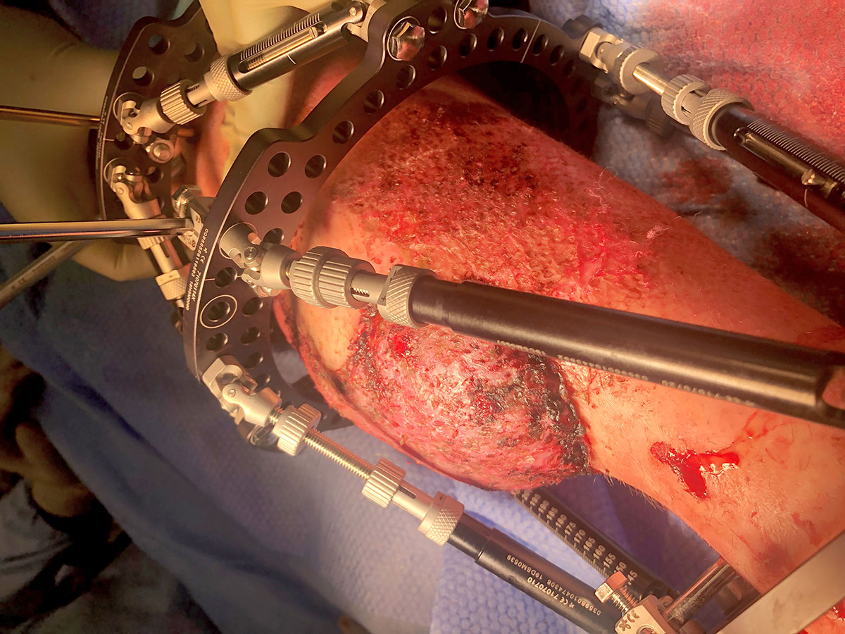
7b Custom Strut Mount utilized to avoid impingement on tissue flap
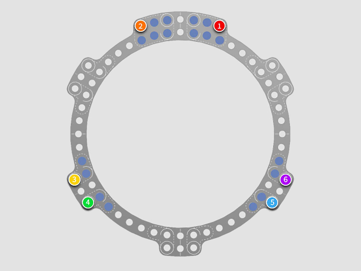
Custom Strut Mount options are shown in blue in the software
In practice there can be difficulties with achieving stability as the subspherical Rings suffer reduced torsional rigidity. Strategies to reduce this risk include the use of rotated 2/3 Ring blocks
(Figures 7d and 7e).
At the time of primary surgery the surgeon should account for likely swelling, and walking to the end of the bed for an axial view of the leg is recommended to reduce the incidence of soft tissue impingement with hardware (Figures 7d and 7e).
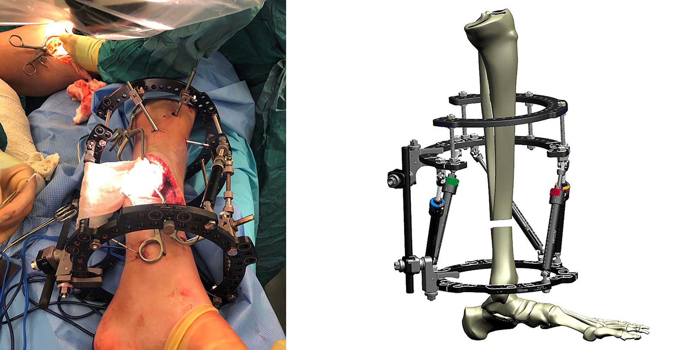
Proximal Ring Block using two offset 2/3 Rings allows soft tissue reconstruction. Note Frame Stabilization tool allowing Strut 3 to be removed temporarily
Early correction vs late correction
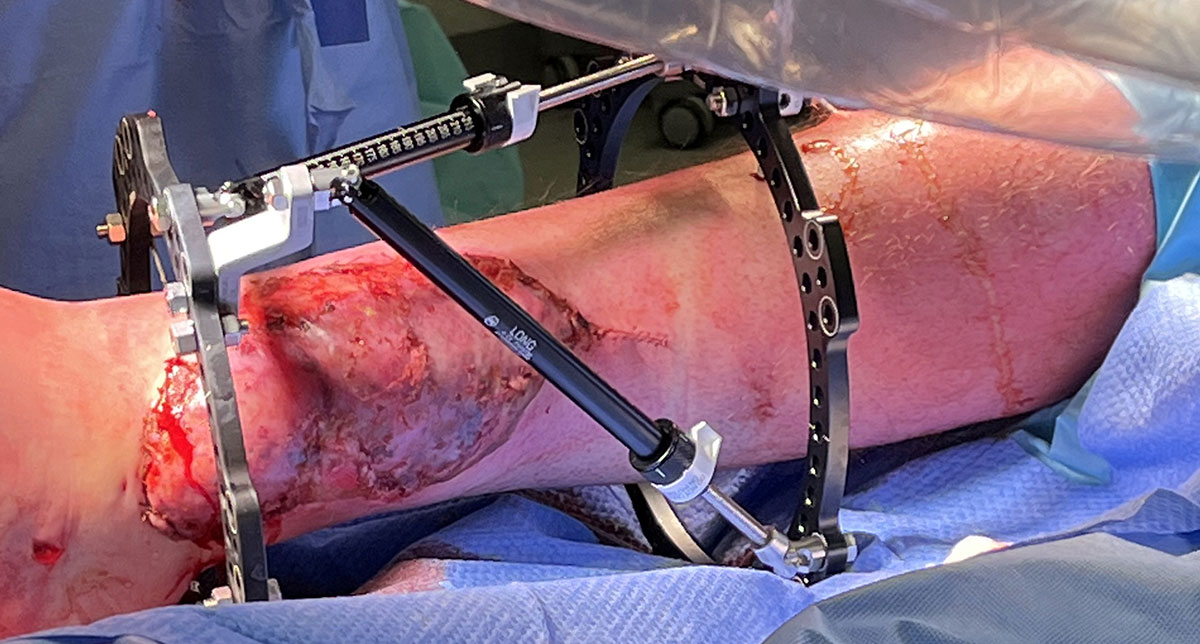
In the majority of cases a sensible strategy is to either place a temporary ex-fix, or the author’s preferred strategy is to place the primary frame on admission at the time of initial debridement. Using a primary spatial frame has some significant added benefits as it allows for the use of “dialled in deformity” and distraction histogenesis for soft tissues. This can allow for the primary closure of soft tissues that would otherwise be unreconstructable (Figure 8a). There is evidence to support this approach4 and, although not ideal for all patients it offers flexibility in terms of reconstruction.
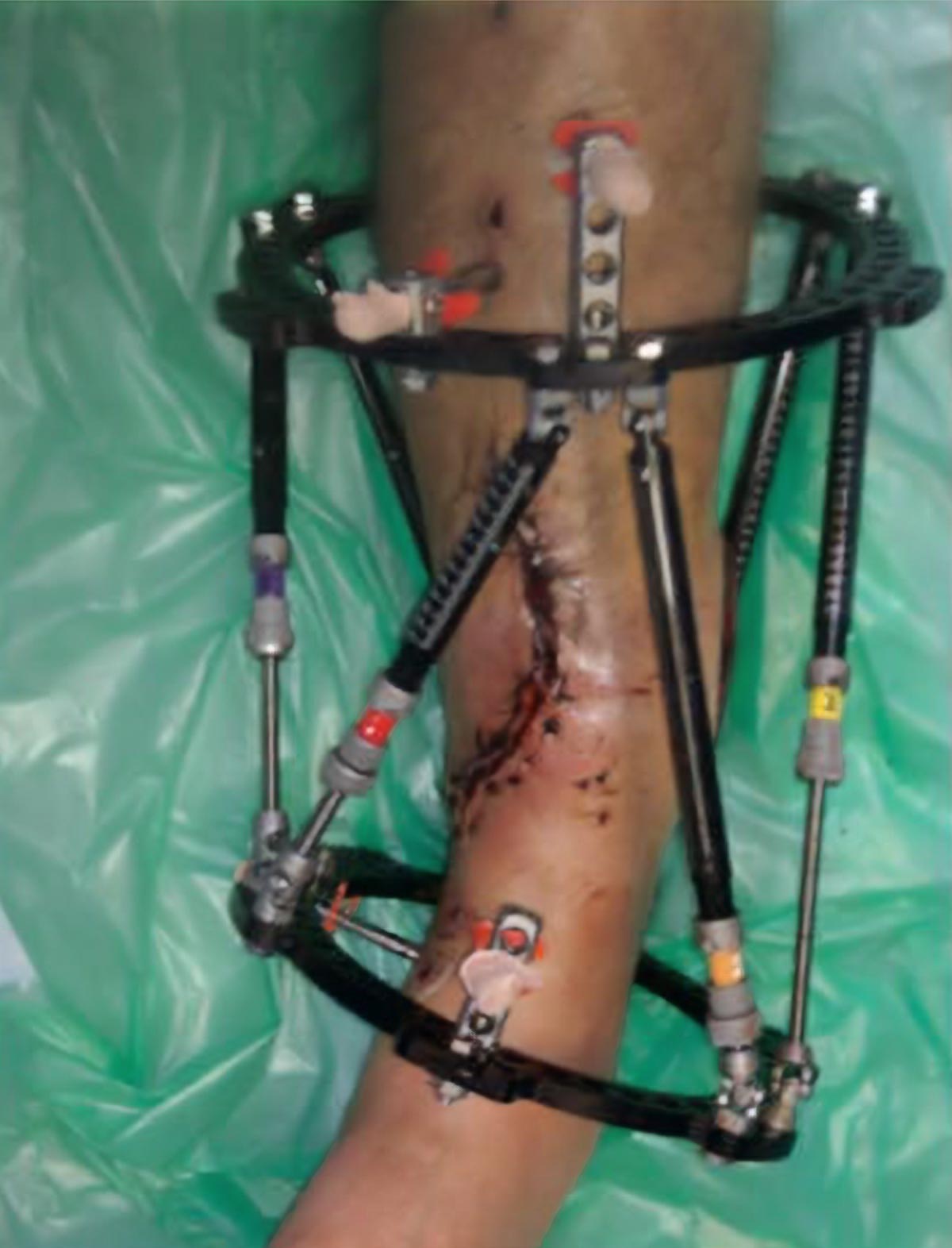
Intentional deformity of the bone to close soft tissue Image courtesy of Om Lahoti, FRCS
Planning for bone transport
While the two-Ring TSF is an adequate construct for the majority of cases where a bone transport is likely to be required, it is ideal to utilise a proximal and distal Ring block with a stable construct including half pins and fine wires at the time of primary surgery. Ideally the blocks would be parallel, allowing for a simple bone transport (Figure 8b); however, sometimes this is not possible and it is more than acceptable to use non-parallel rings in association with a balanced cable or utilise the Hexapod in a “Rings first” mode to correct to parallel rings. The primary consideration is getting the rotation correct as this is impossible to correct once bone transport is underway.
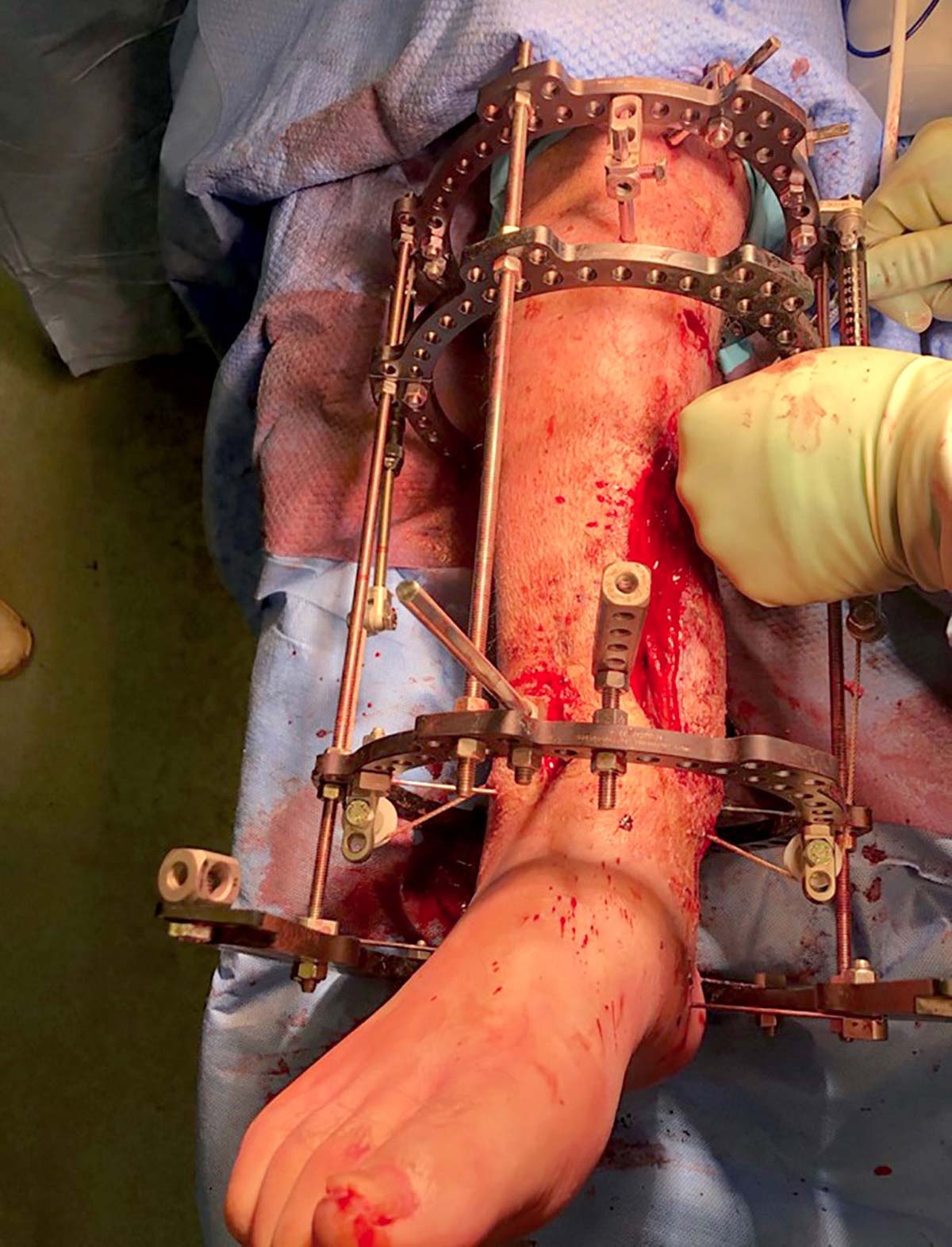
Special consideration – The open pilon fracture
The open pilon provides a special case, with poor soft tissues, and often complex intra-articulate fragments. Whatever strategy is chosen with regards to a delayed or acute TSF application, we would recommend the use of fragment-specific fixation with either lag screws or adjunctive mini plates to reduce and hold the articular block prior to TSF application.
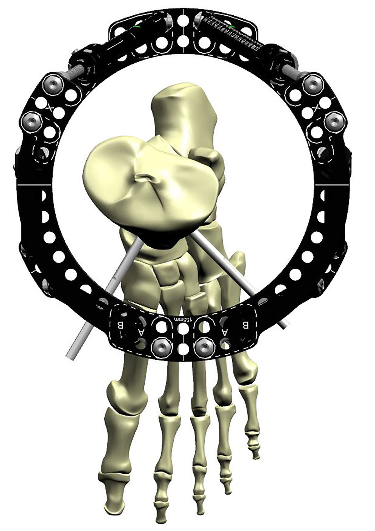
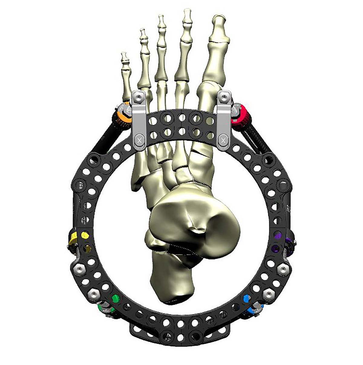
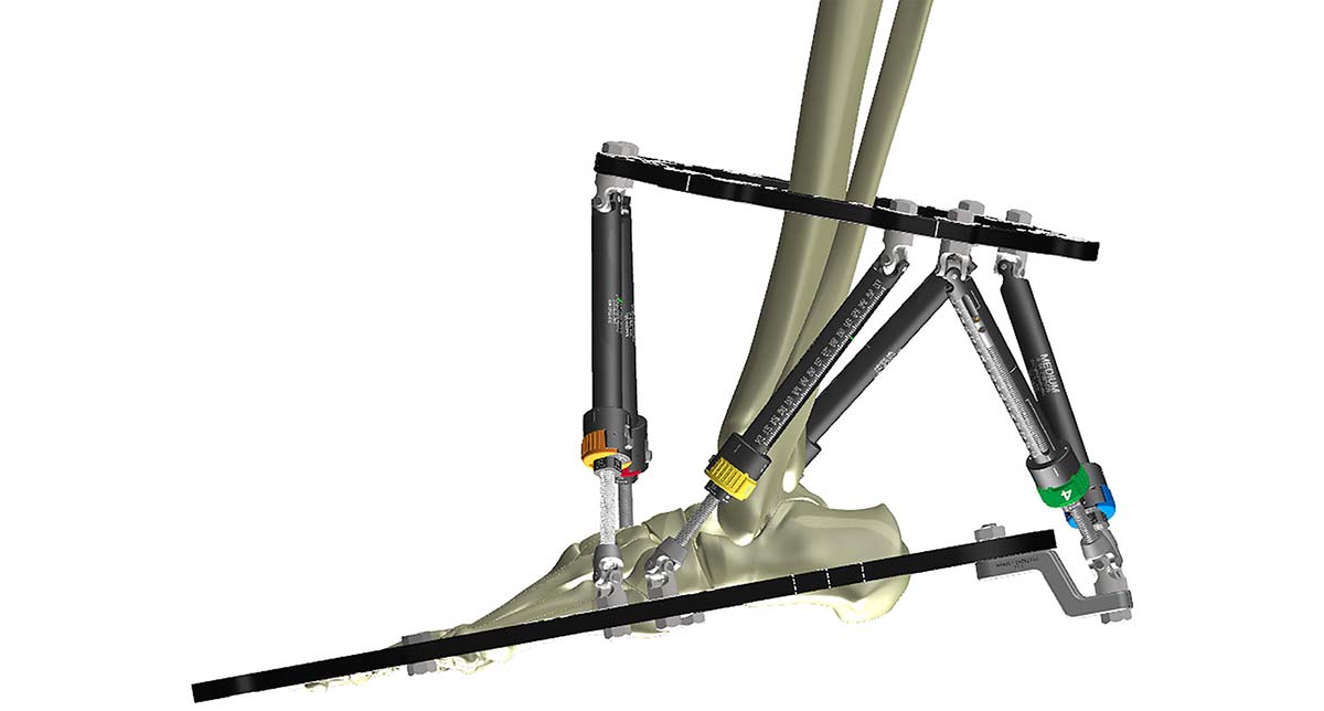
In many cases the ankle will not need to be bridged. In situations where bridging is necessary, this can be achieved with a Foot Ring (Figure 9a). An alternative strategy is a Ring block using a Half Ring connected to the distal 2/3 Ring (Figure 9b). This approach achieves bridging across the joint and still allows access to soft tissues for reconstruction.
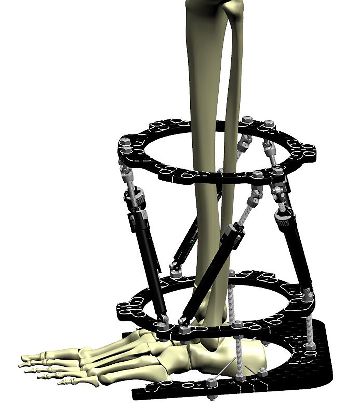
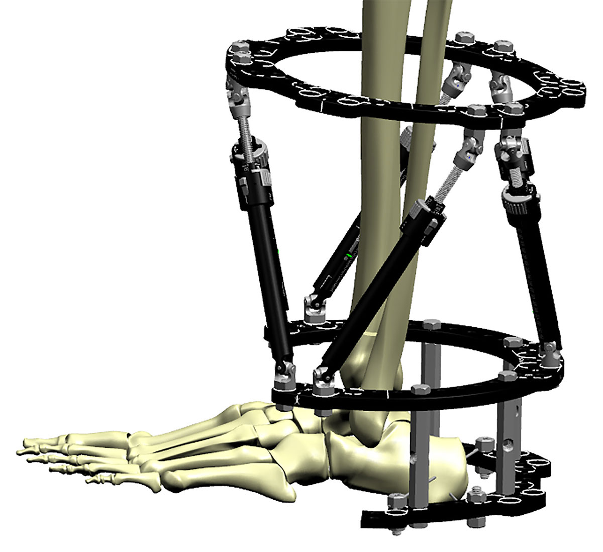
Special consideration – Using the Compass Hinge across a joint
It is worth considering the use of hinges which can be required in the ankle, knee or sometimes in the elbow. The approach to bridging the knee is simple:
- Undertake thorough wash-out and debridement, bridging the knee or ankle with a spanning external fixation.
- Once soft tissues are amenable, undertake a joint reduction and fixation.
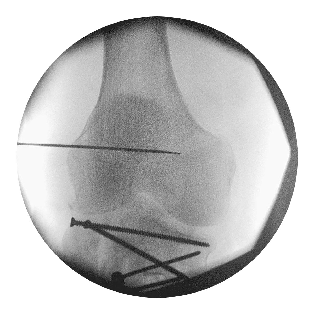
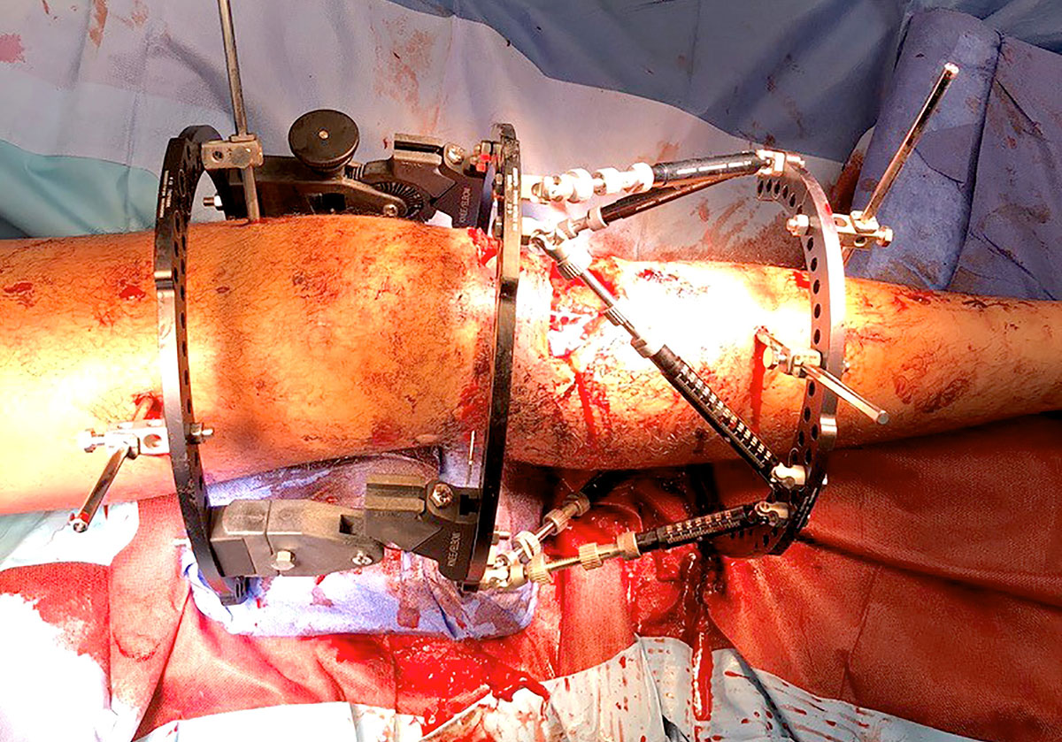
- Apply the Compass Hinge pair first at the isometric point using a fine wire for guidance (Figure 9c). The femur can be controlled with a 2/3 205mm or larger Ring, and the tibia should also be controlled with a 2/3 Ring far enough distal to allow flexion. Position of the matching tibial Ring should be undertaken first as this will likely also need fine wires to neutralise the joint fragments.
- The Hexapod can then be built below to provide a complete construct (Figure 9d).
Software
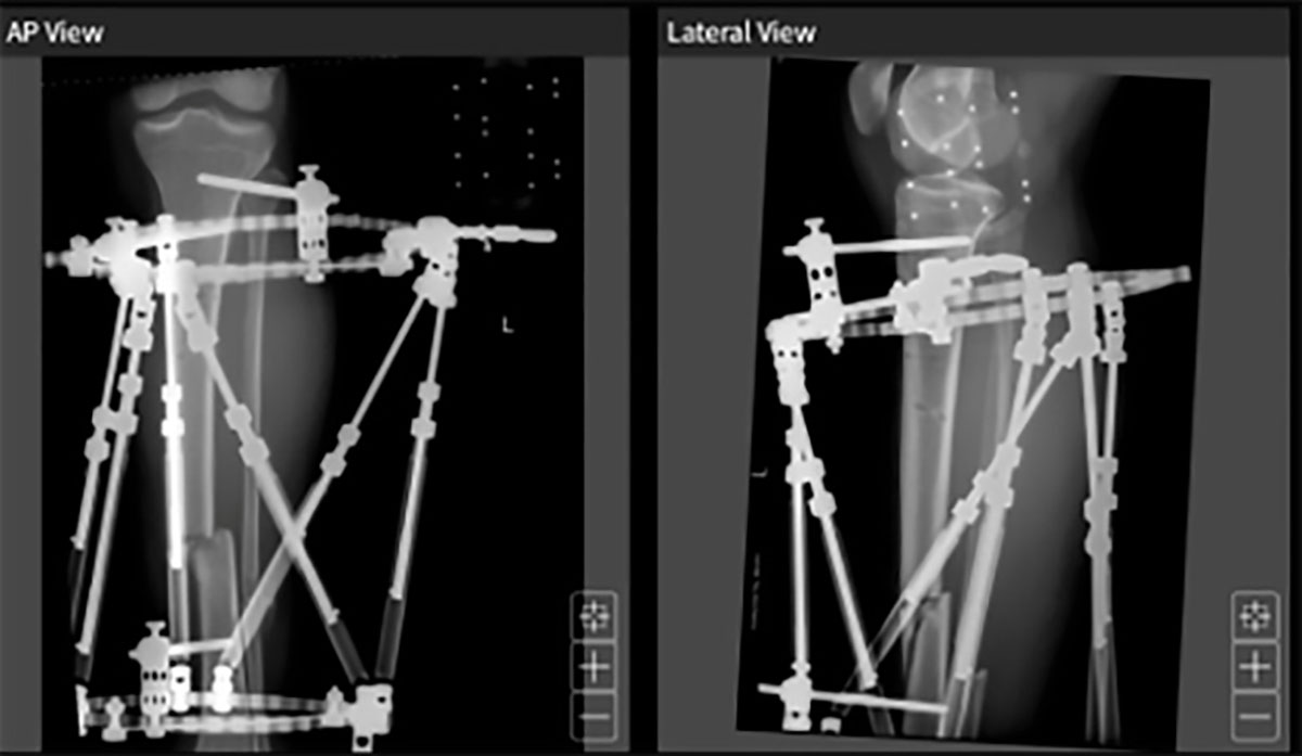
TraumaDots is a deformity analysis technique designed to digitally reduce displaced fracture fragments. It has the advantage of simple application and the ability to reduce a bone based on four reduction keys and their matching reduction points (Figure 10a).
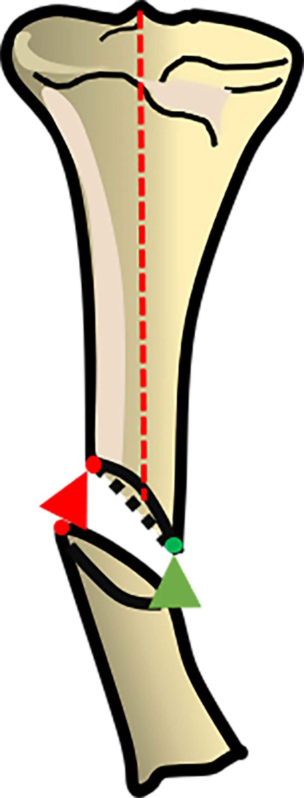
When undertaking deformity correction for open fractures TraumaDots is the preferred method. Clear near orthogonal plain film radiographs are required in order to achieve the reduction and ideally would be centered on the fracture site not the proximal Ring (Figure 10b).
Identification of the reduction keys and matching reduction points (Figure 10c) does not need to cover the whole width of the bone, but will be more accurate if points on either side of the projection are chosen.
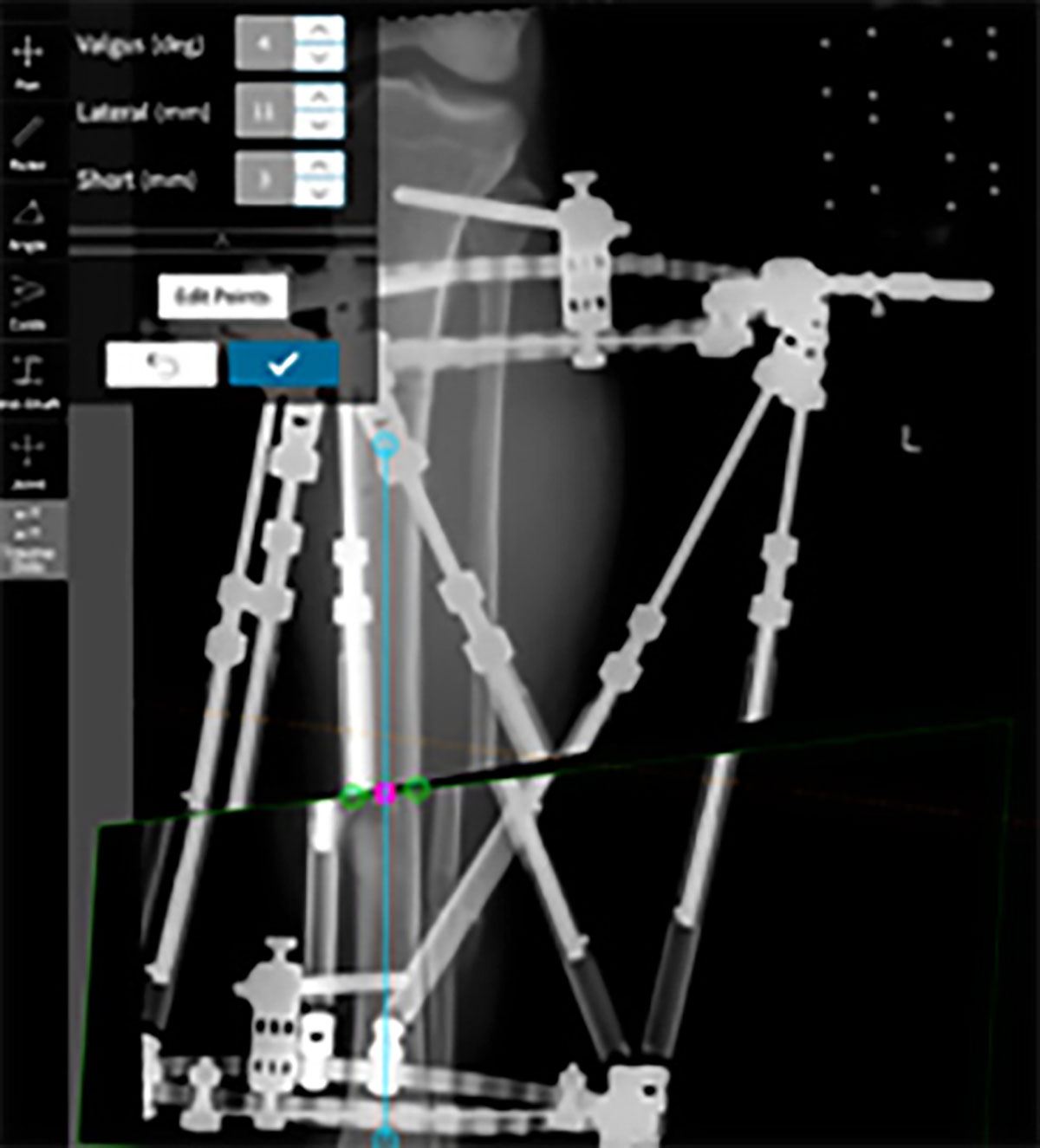
Provisional reduction can then be adjusted as necessary with “nudge” tools and the reduction parameters checked.
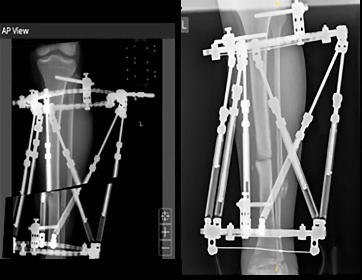
In my experience, this method reliably leads to accurate corrections and reduction of the fracture with a single step (Figure 10d).
References
- France J, Tucker A, Norrish A, Taylor A, Ollivere B. Management of Tibial Fractures Using the TAYLOR SPATIAL FRAME. Orthop Procs. 2022;104-B(SUPP_5):22-22.
- Gopal S, Majumder S, Batchelor AG, Knight SL, De Boer P, Smith RM. Fix and flap: the radical orthopaedic and plastic treatment of severe open fractures of the tibia. J Bone Joint Surg Br. 2000 Sep;82(7):959-66.
- Al-Hourani K, Stoddart M, Khan U, Riddick A, Kelly M. Orthoplastic reconstruction of type IIIB open tibial fractures retaining debrided devitalized cortical segments – The Bristol Experience 2014 to 2018. Bone Joint J. 2019;101-B:1002–1008.
- Lahoti O, Findlay I, Shetty S, Abishetty N. Intentional Deformation and Closure of Soft Tissue Defect in Open Tibial Fractures With a Taylor Spatial Frame—A Simple Technique. J Orthop Trauma. 2013;27:451–456.
