Configuring a TSF◇ Butt Frame
Hemant Sharma, FRCS; Hull Royal Infirmary, UK
The views and opinions expressed in this section are those of the surgeon.

Introduction
Butt joint is a carpentry term which refers to the technique where two pieces of material are joined by simply placing the end or face together. The term was usedby Dr. J Charles Taylor to develop the nomenclature for foot and ankle frames.
Foot deformities are often three-dimensional resulting from a variety of causes. These deformities can be associated with poor soft tissue, infections, leg length discrepancies, etc. Neuromuscular conditions/syndromic feet can cause a particular challenge in correction. Although acute corrections are reasonable, aggressive acute corrections, particularly in presence of scar tissue, can result in neurovascular compromise.
Deformity can result in calluses, pain, stress fractures, ulcerations, infections, difficulty in footwear and compromised function. Differentiation between a progressive condition like Charcot Marie tooth disease and a static condition like cerebral palsy is very helpful in planning.
Soft tissue correction is an integral part of surgical treatment. Secondary compensatory deformities and primary associated deformities must be identified and tackled to provide a plantigrade foot to the patient. Severity of deformity and aetiology directs the treatment strategy.
Detailed history and thorough clinical examination, mobility of different joints and forefoot hindfoot relationship (Coleman block test) should be documented.
Routine pre-operative foot X-rays are not always useful but help in determining the apex of the deformity. Post-operatively, X-rays are hard to interpret, but useful to rule out any subluxations. Foot deformity corrections are best judged clinically. 3D CT scans and recently 3D-printed models of the deformity are very helpful in analysis and surgical planning.
Patient expectations must be aligned with feasible and realistic goals for satisfactory outcome.
Applications
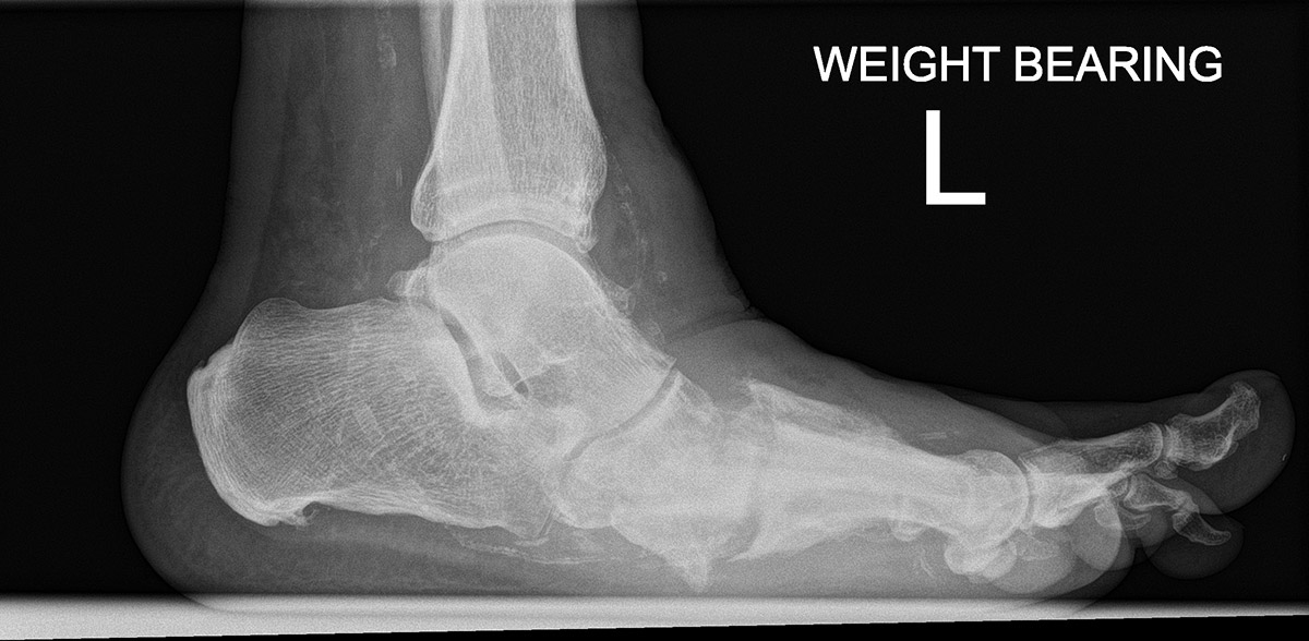
- Mid-foot deformities; rocker bottom/cavus deformity with/without forefoot deformity (adduction, abduction, pronation and supination); secondary to Charcot disease, non-Charcot neuropathic deformity
- Equino-cavo-varus deformity, where other components of the deformity except cavus are acutely corrected and stabilized.
- Midfoot malunion secondary to trauma
- Lisfranc and midfoot fractures
The goal of treatment is a stable plantigrade foot.
Construct possibilities
1
Correct Hindfoot
2
Correct Forefoot
or Midfoot
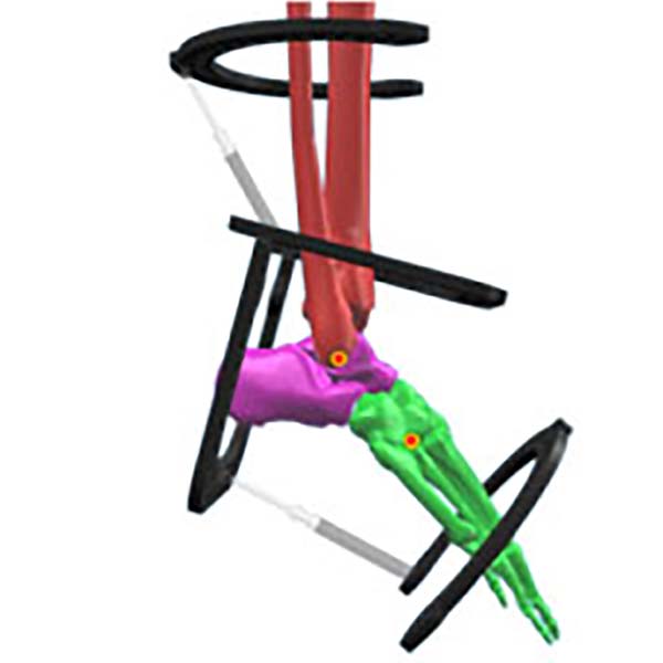
1
Correct Tibia
2
Correct Forefoot
or Midfoot
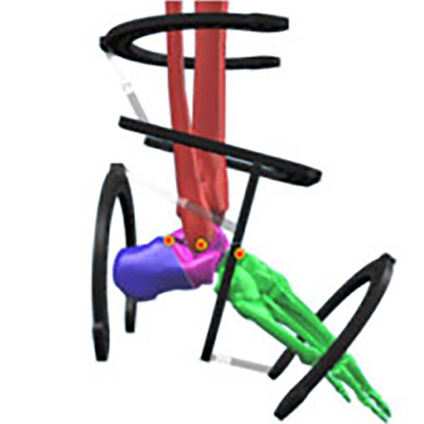
1
Correct Tibia
2
Correct Hindfoot
3
Correct Forefoot
or Midfoot
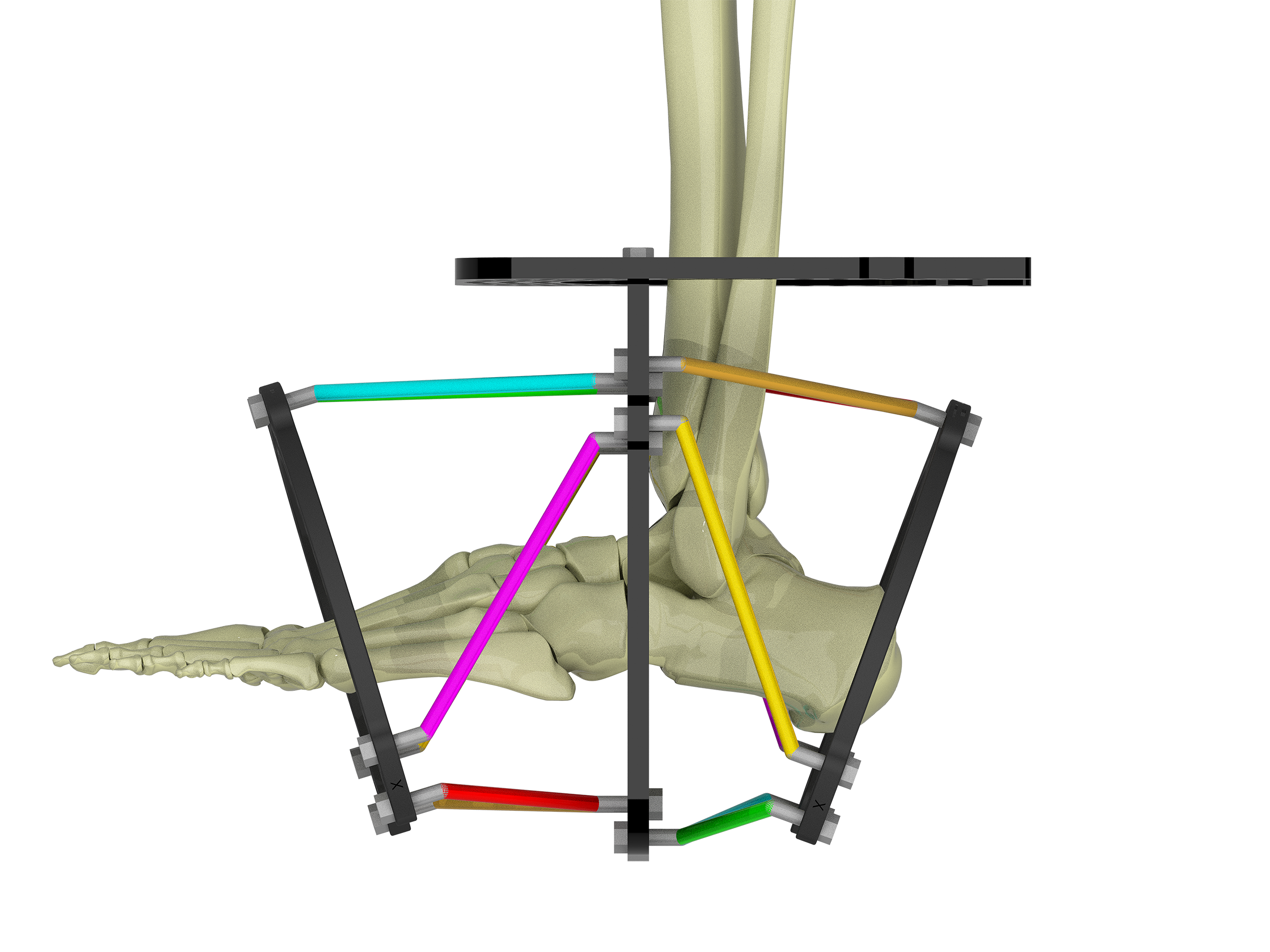
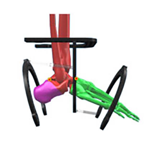
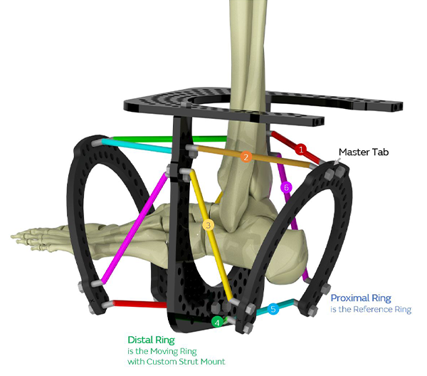
Forefoot Frame – Distally referenced
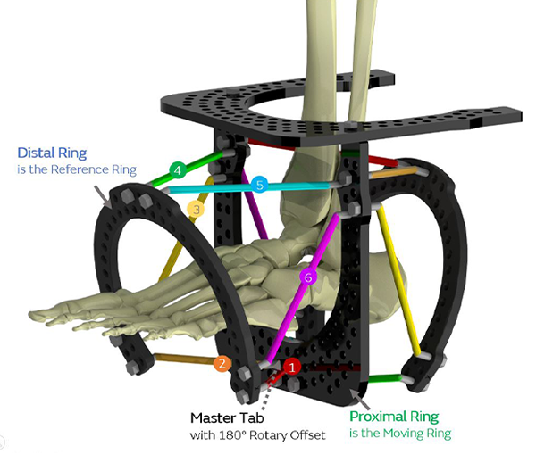
Hindfoot Frame – Proximally referenced
Surgical technique
- Steindler’s procedure to release plantar fascia (if required)
- First metatarsal may be plantar flexed and may need dorsal closing wedge osteotomy
- Cavus is often associated with equinus, which can be corrected acutely either by percutaneous/open Tendo Achilles lengthening.
Proximal Ring Block
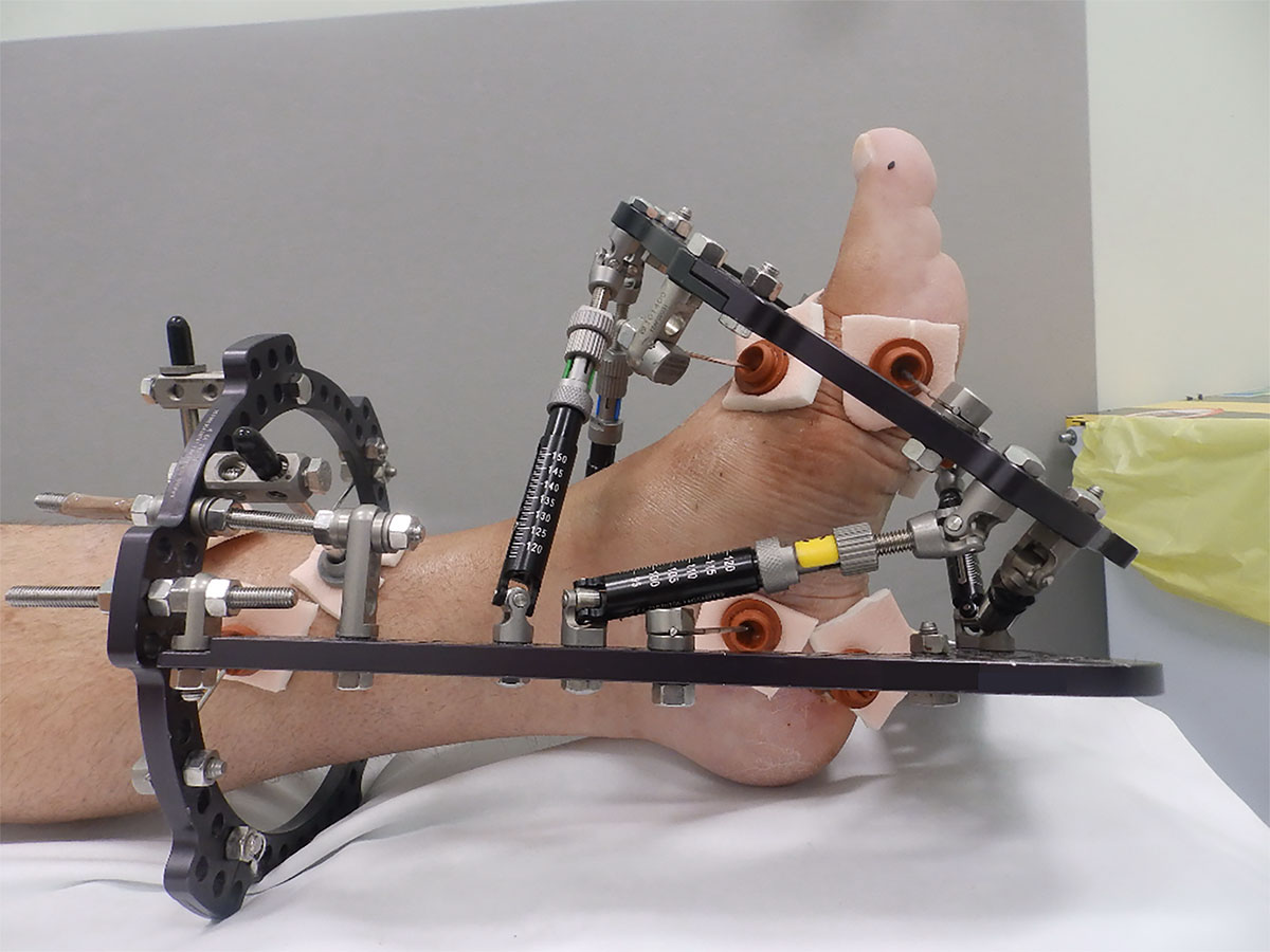
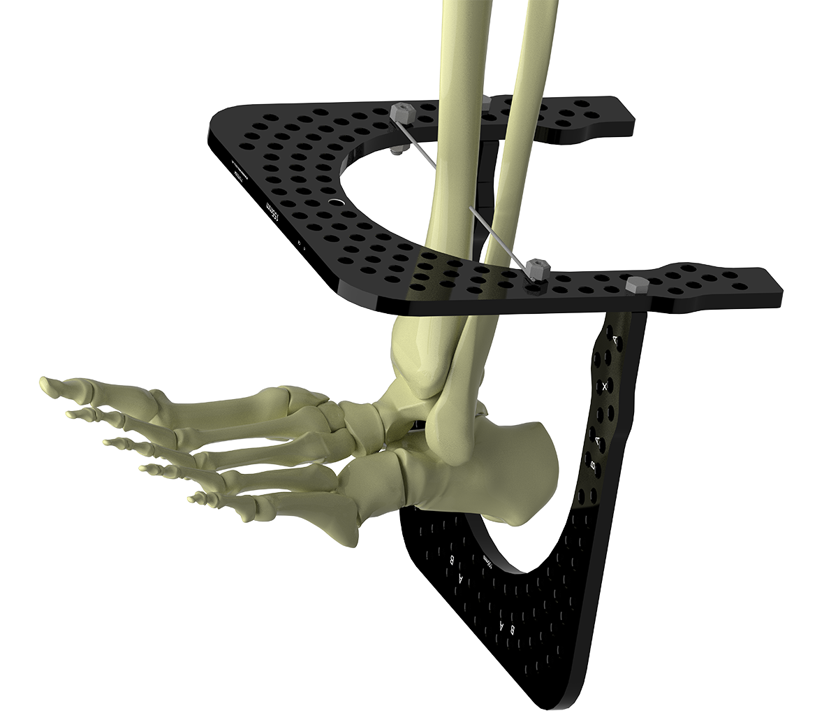
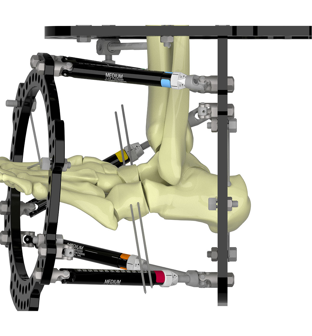
Select the appropriate size U-Ring for the tibia and matching U-Ring to configure the “butt” construct (Figure 2a). Sometimes a two-ring block is necessary on the tibia, especially for a neuropathic limb or if a stiffer construct is required.
Insert a transverse wire through the Tibia as a reference wire and tension to 130kg. This wire should be proximal enough on the tibia to leave enough space between the tibial Ring and planned distal foot Ring to prevent impingement. Half pins may be used instead of Wires.
The foot U-Ring is attached posterior to the tibia and should be parallel to the axis of the tibia, allowing two-finger-breadth clearance of the heel pad (Figure 2b).
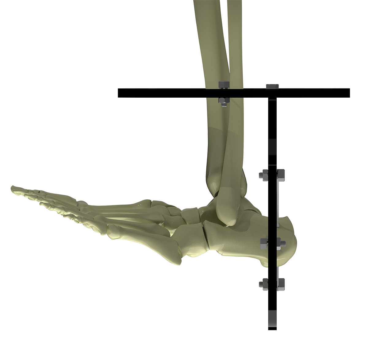
Place two Olive Wires with as much crossing angle as possible in the calcaneus.
Tension both wires at the same time. Tensioning one wire at a time results in loosening of the first wire when the second wire is tensioned (Figure 2c).
Place two Half Pins each on a 2H or 3H Rancho above and below the tibial Ring, ensuring adequate fixation spread. The first pin is usually placed directly anterior, above the Ring. The second is below the Ring in the anteromedial position.
Tip – These Pins are best placed after Strut application.
Fixation of the foot
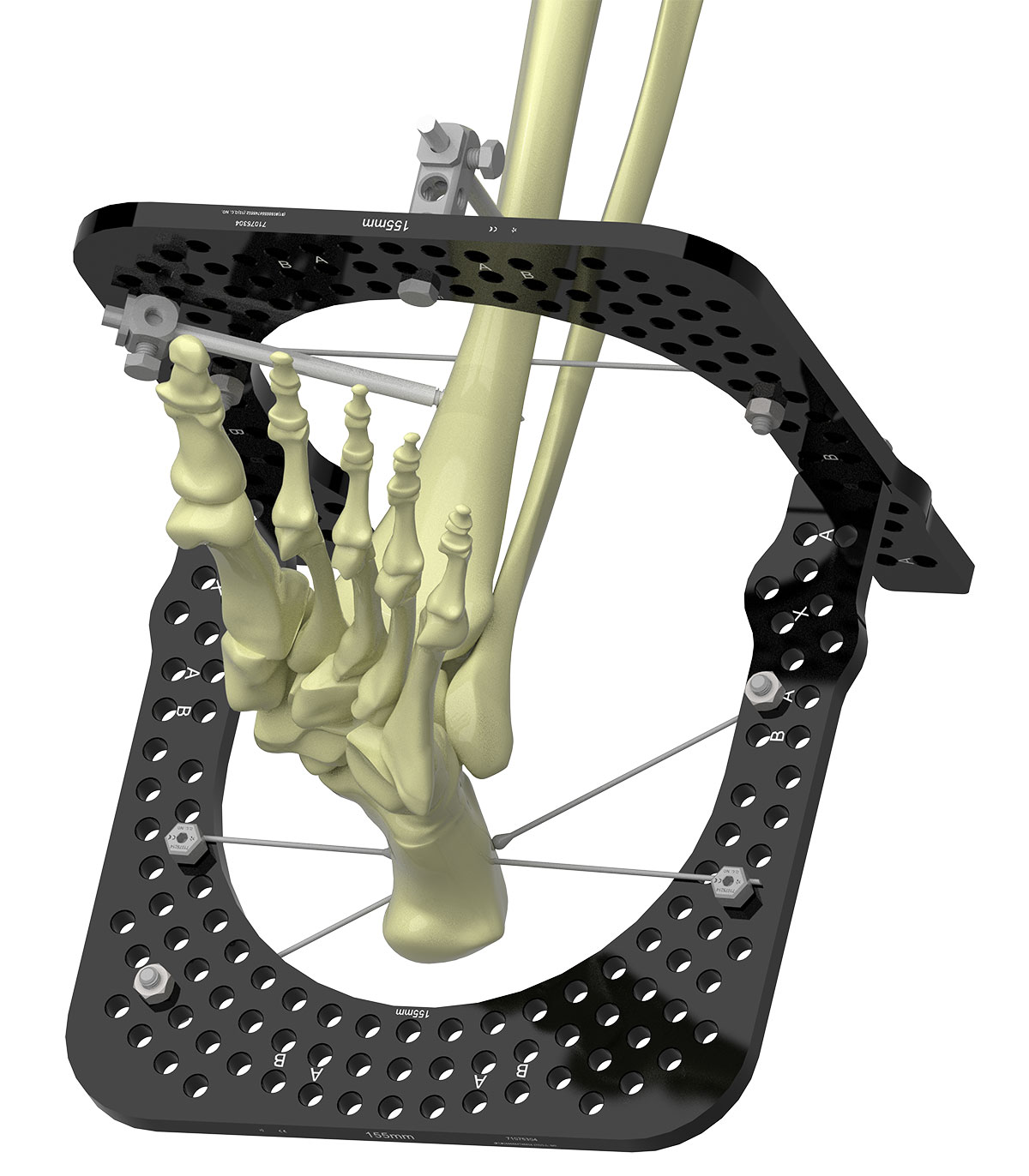
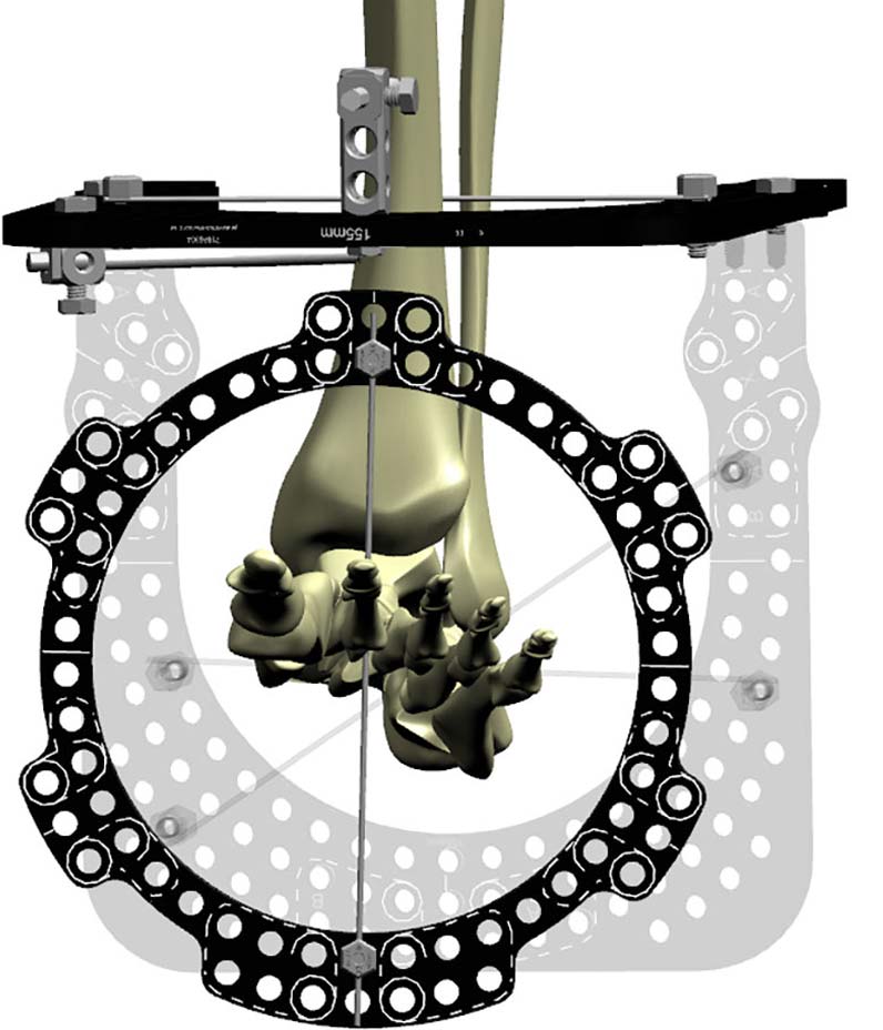
The second metatarsal is the key to stable foot fixation. Place a dorsal to plantar wire just proximal to second metatarsal neck. This wire should be drilled to the far cortex and tapped through the soft tissue of the plantar surface.
Secure the wire along the equator lines of an appropriate size Full Ring. Orient the Ring to align with the rotation and pronation or supination of the foot. Setting the Ring up in this manner ensures AP offset is “0” (Figure 3a).
You can also reference the equator lines on the dorsal and plantar aspect of the Ring. Aligning with the second metatarsal reduces the lateral offset to “0.”
Confirm that there is enough space for the Foot Ring and it does not impinge on the tibial U-Ring.
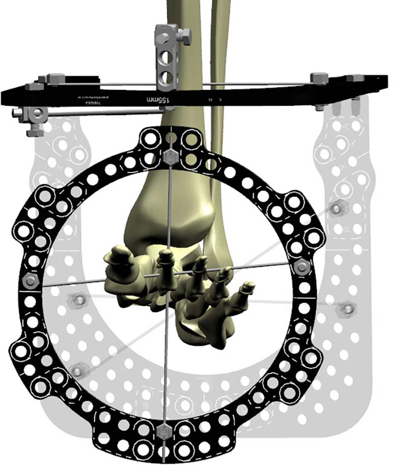
Place a second Olive Wire proximal to Ring (Figure 3b).
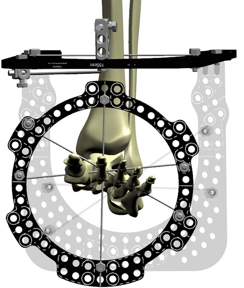
Place a third Olive Wire from lateral to medial through metatarsal five, four, three, proximal to the Ring. (Figure 3c).
Strut application
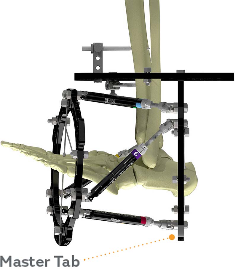
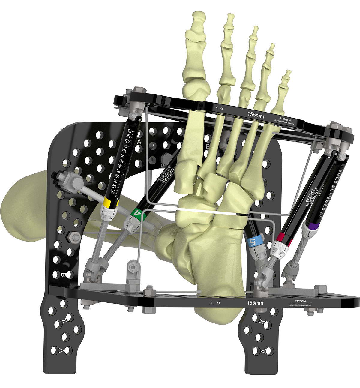
The Master Tab where Struts 1 and 2 meet is on the foot U-Ring resulting in 180° rotary frame offset (Figure 3d). Verify the simulated graphics in smart-TSF.com align with the actual construct.
Osteotomy
The author prefers a Gigli saw osteotomy, though drill and osteotome technique is equally acceptable.
Gigli saw
Some Struts may be detached to create space. This is a four-incision technique; usually performed from medial to lateral; dorsomedial, dorsolateral, plantar medial and plantar lateral.
A periosteal elevator is used to create the sub-periosteal passage. Passage on the plantar side due to concavity of the arch can be challenging. Always keep the periosteal elevator on the bone. A long curved artery clip is pushed through the path and #1 braided suture passed. The Gigli saw is then passed.
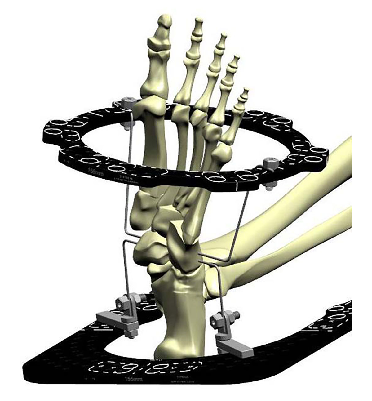
Pass two Smooth Wires 5-7mm apart at the planned osteotomy level. These wires will ensure that Gigli saw stays in the desired osteotomy site (Figure 4a).
The osteotomy is performed and Gigli saw removed.
Bend the wires to the Ring using the hole on the handle of a Wrench and connect to the Ring with Plates, Posts and Bolts (Figure 4b). These stirrup wires serve to control the distraction at the osteotomy and protect the surrounding small joints from distraction during the correction.
Drill and osteotome
Two to three drill holes are made from medial to lateral side, respecting the concavity of the metatarsal arch (Figure 4c).
Osteotomes do not provide adequate feedback and it can be difficult to judge completeness of osteotomy. Manipulate the osteotomy acutely on table to confirm completeness.
Struts can now be re-connected.
Wiring of the toes
If significant deformity is present or there is history of prior surgery with toe deformities, the toes can be wired and secured to the frame. In most situations the toes can be left free but post-operative regular and aggressive stretching is mandatory, especially in correction phase.
Classic software planning
Deformity analysis
Draw a line from centre of the ankle.
Draw a line along the second metatarsal shaft. Where these lines meet is the apex of deformity and CORA.
Define origin and corresponding point and calculate deformity.
Tip – Always add shortening in the planning to avoid impingement.
Tip – Defining the Corresponding Point at the CORA avoids translation.
Mounting parameters
AP and lateral offset is “zero” if the Reference Ring has been mounted as described.
Rotary frame offset is “180° pronation.”
Tip – Verify that Strut orientation in software graphics align with the applied frame
SMART TSF◇ software planning
The Beacon can be attached to either the proximal or distal Ring on the foot, though attaching to the distal Ring on the forefoot reduces the risk of the Beacon hitting the surface the foot rests on during X-ray capture. If not using the Beacon, choosing a Distal Referencing strategy will make manual calculation of Mounting Parameters easier.
Tips for distal referencing
– Angulations and rotations stay the same
– Translations are reversed
Deformity calculations
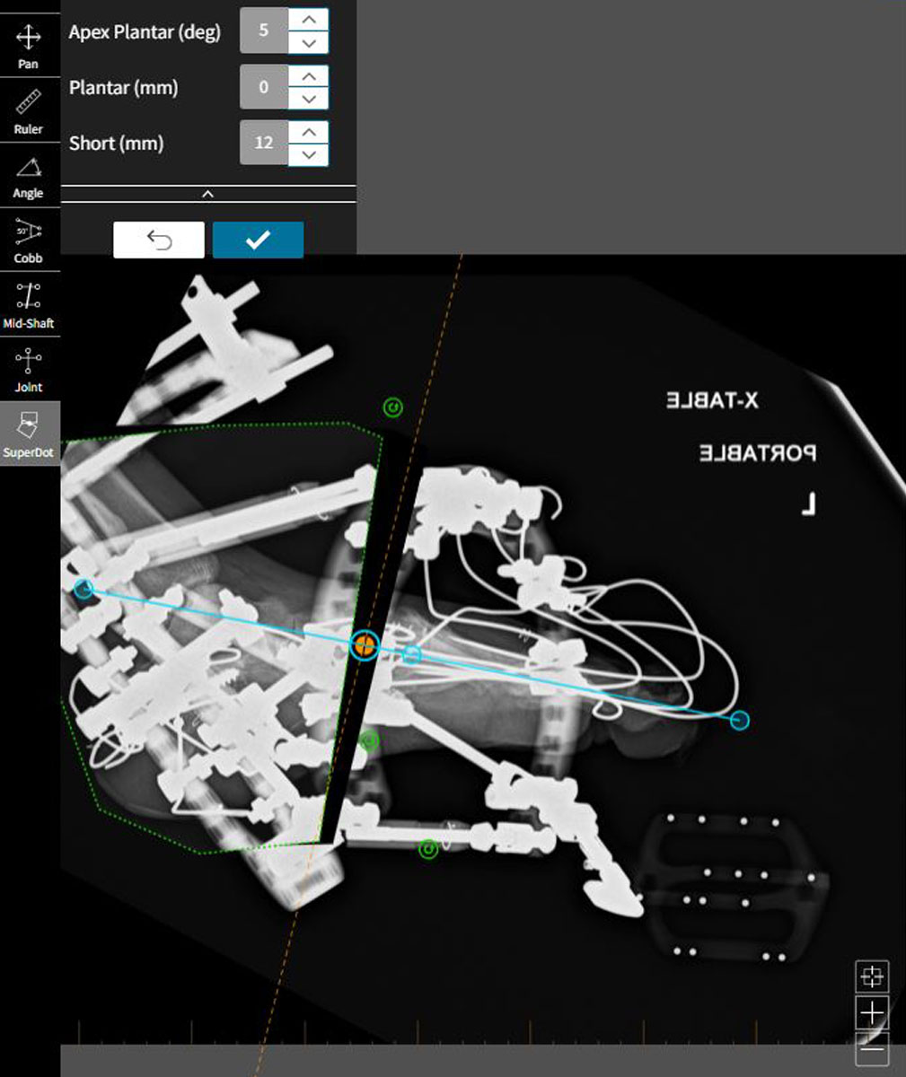
The traditional Origin & Corresponding Point strategy can be used, whereby the deformity measured on X-ray is input manually on smart-TSF.com. The new SuperDot analysis method, however, simplifies deformity analysis and correction planning in the foot.
SuperDot
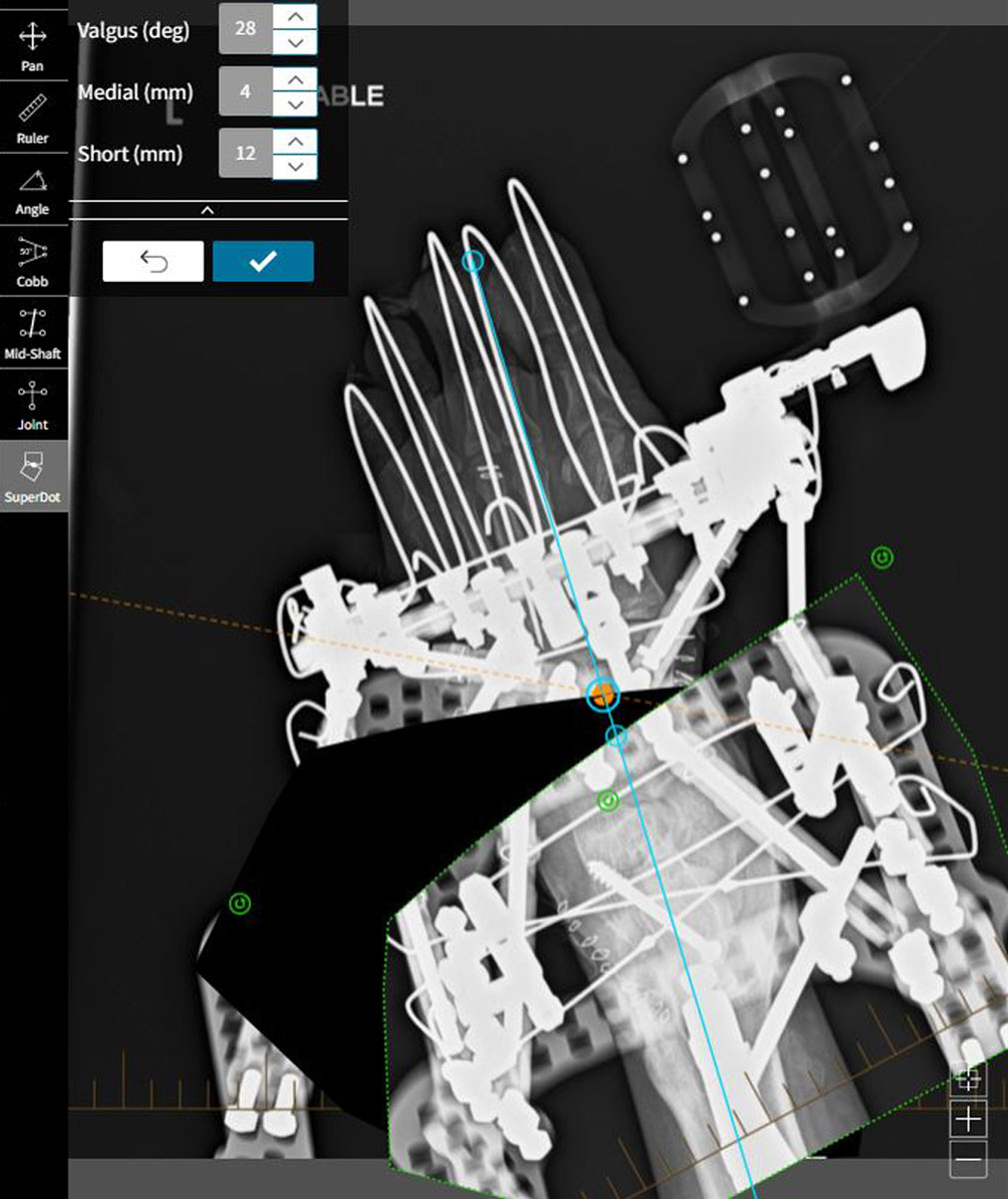
On the AP view, segment proximal to the osteotomy is traced out and becomes the Moving Fragment.
The segment distal to the osteotomy is the Reference Fragment. The reference axis is positioned to align with the second metatarsal.
The SuperDot is placed on the osteotomy, typically at the midpoint.
The moving fragment is picked up and positioned as desired, using the reference axis as the indicator of normal alignment.
The deformity is thus calculated. Adding millimeters of “Short” helps reduce impingement during the angular correction.
Select the check mark to accept these deformity parameters.
The same is repeated on the Lateral view, once again aligning the reference axis with the second metatarsal.
Rotation is a clinical assessment.
Post-operative
ILIZAROVTM Sponges applied and held with clips or bungs
Nerve catheter block to continue for 48-72 hours, however if nerve catheter is not used, then patient-controlled analgesia (PCA) must continue for 48-72 hrs.
First dressing change in 48hrs should be done prior to stopping the nerve catheter/PCA.
Immediate physiotherapy is started.
Corrections should be started in 48 hours with normal pace defined by soft tissue tension.
Tip – There is a risk of premature consolidation.
Out-patient physiotherapy should be scheduled prior to discharge. Patient must attend twice-weekly physiotherapy. Toe stretching
is paramount.
Follow up in one week, and weekly until corrections are completed. Thereafter, six to eight week follow-up is usually adequate until the frame is ready for removal.
Progress of the correction should be monitored using X-rays and, more importantly, clinically-observed shape of the foot.
Post frame removal
Follow-up at two weeks can be with a specialist nurse, with six-week follow-up by the surgeon. Patients should be seen once more at one-year post-op and are usually ready to be discharged at this time. Once the osteotomy has healed, there is no risk of recurrence.
Patients frequently need customised insoles or shoes for pressure distribution, especially if there is neurological compromise. Diabetic patients are more regularly followed up with the specialist team.
Complications
Possible complications include toe contractures, MTP joint subluxation and pre-mature consolidation.
