Fundamental principles of stable frame construction
J. Tracy Watson, MD; SSM Health St. Louis University Hospital, MO
The views and opinions expressed in this section are those of the surgeon.

Introduction
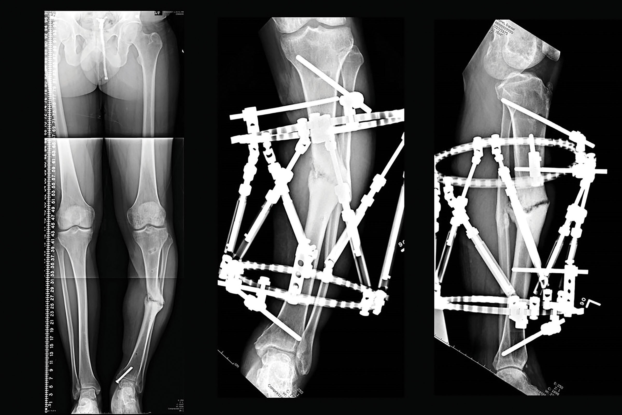
One of the biggest advantages of using a TSF◇ for circular ring fixation is the ability to modulate the biomechanics of the construct based on the pathology you are treating. Fracture healing requires a degree of flexibility to induce fracture micromotion and thus proceed with secondary callus formation. Gradual “downgrading” of construct stability, or “dynamization” is also desired toward the end of treatment to allow for controlled fracture remodeling. This is in distinction to treating a hypertrophic nonunion with deformity where a relatively rigid frame is required to provide an adequate distraction force required to correct a stiff nonunion (Figure 1).
However, the construct must allow for the combined stability of the frame augmented with the additional stability afforded by distraction forces of the soft tissues. The use of distraction osteogenesis also requires a distinct mechanical environment to provide stability to the corticotomy site to protect and promote the initial neovascularization and further the progression of the regenerate. Yet as the healing of the regenerate progresses, more dynamic axial micromotion is required to promote regenerate maturation and reverse dynamization (more stable) is also necessary for remodeling to allow for frame removal. These constructs all have in common the need for a basic frame that is stable throughout the range of application indications.
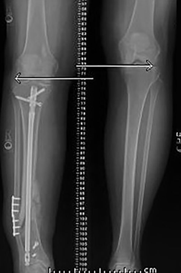
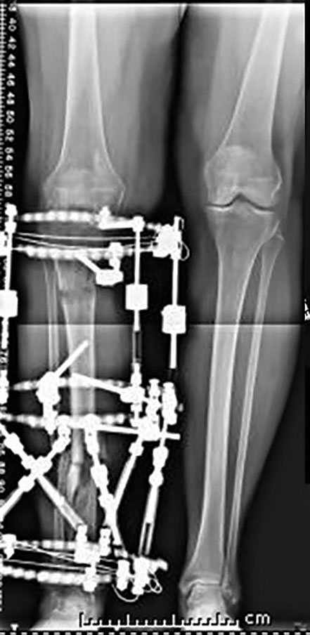
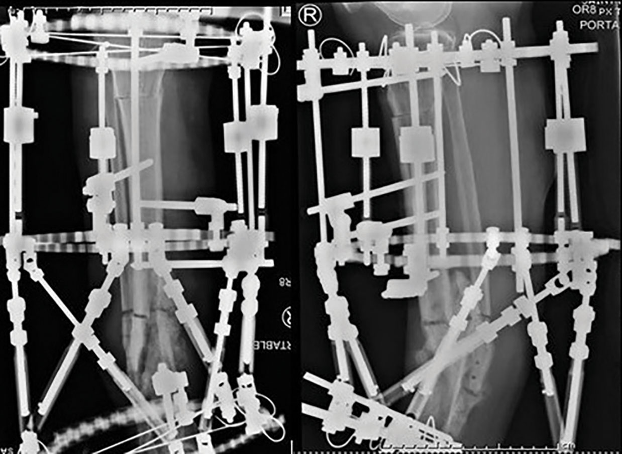
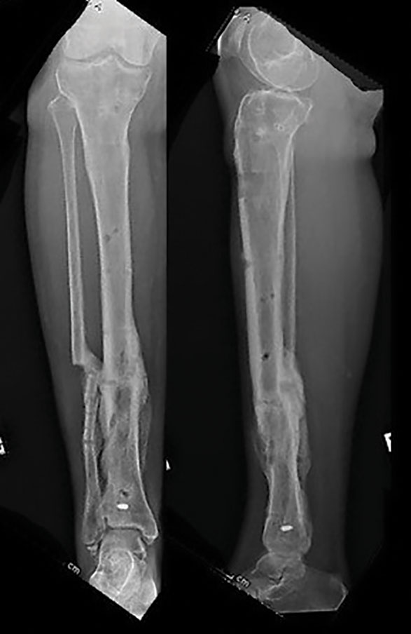
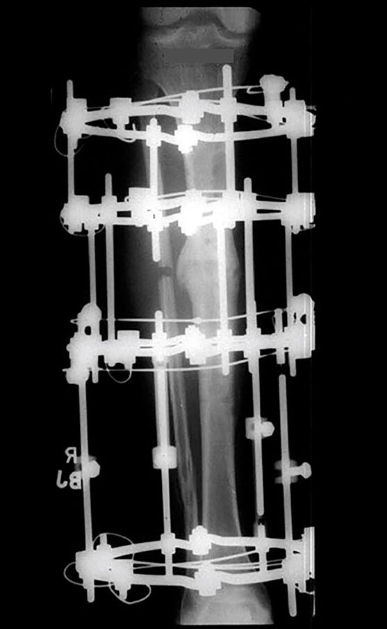
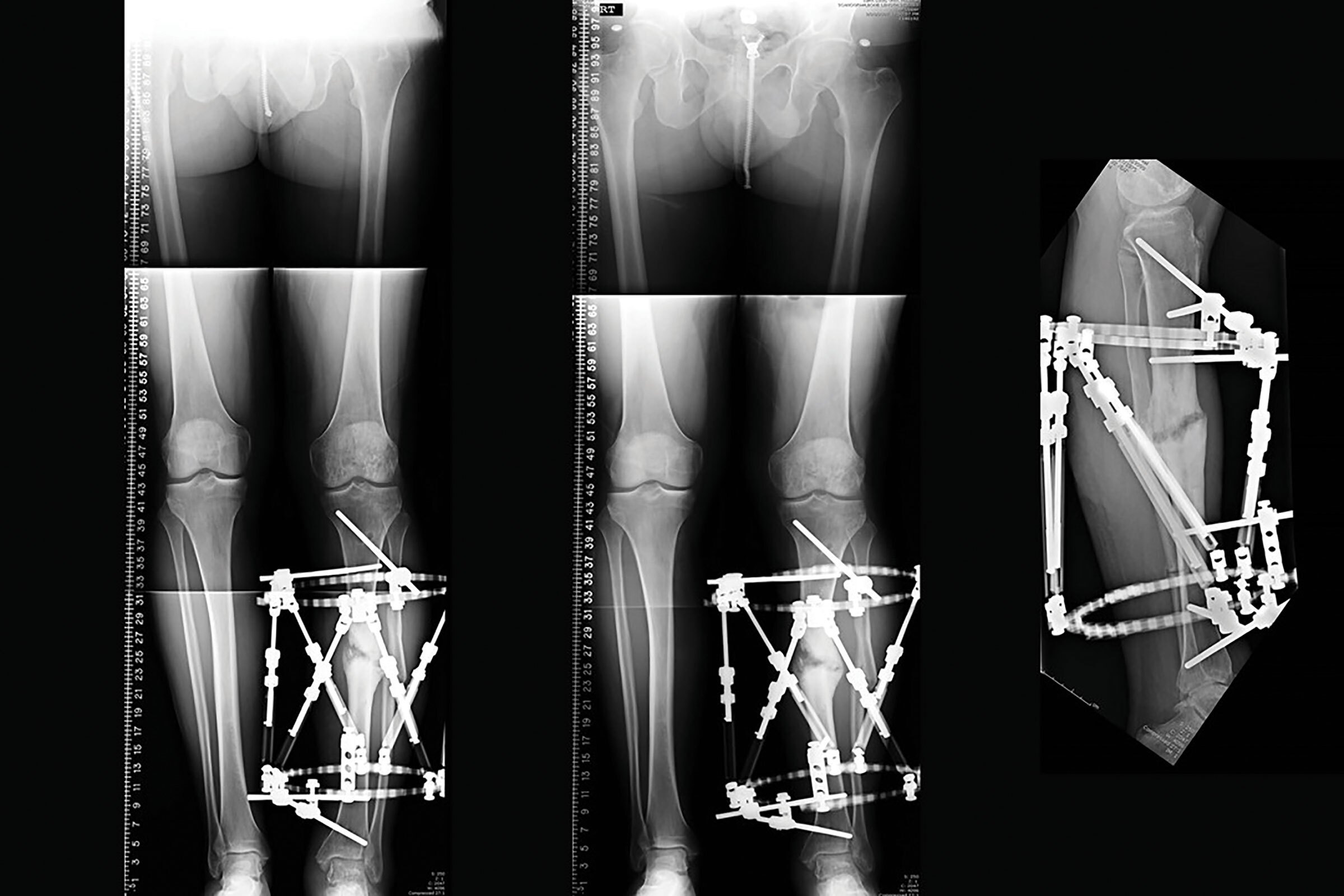
Figure 1
Hypertrophic nonunion with leg length discrepancy, treatment initially requires a rigid frame to bridge the three limb segments.
1. The proximal limb segment above the corticotomy for distraction and resolution of the leg length discrepancy.
2. The intercalary limb segment between the proximal corticotomy and the hypertrophic nonunion site. Distraction across the nonunion to correct the deformity and heal the nonunion.
3. Distal limb segment below the nonunion which requires stability to allow for this bifocal transport to progress.
Terminology
Limb segment
The segment of bone above a fracture site is a limb segment. Likewise, the bone below the fracture site is also another “limb segment.” The area of bone above a corticotomy is a limb segment, as is the bone below the corticotomy, or the regenerate.
The regions of bone above and below a nonunion site are both limb segments. Similarly the bone above a joint contracture is a limb segment as is the bone below the joint contracture.
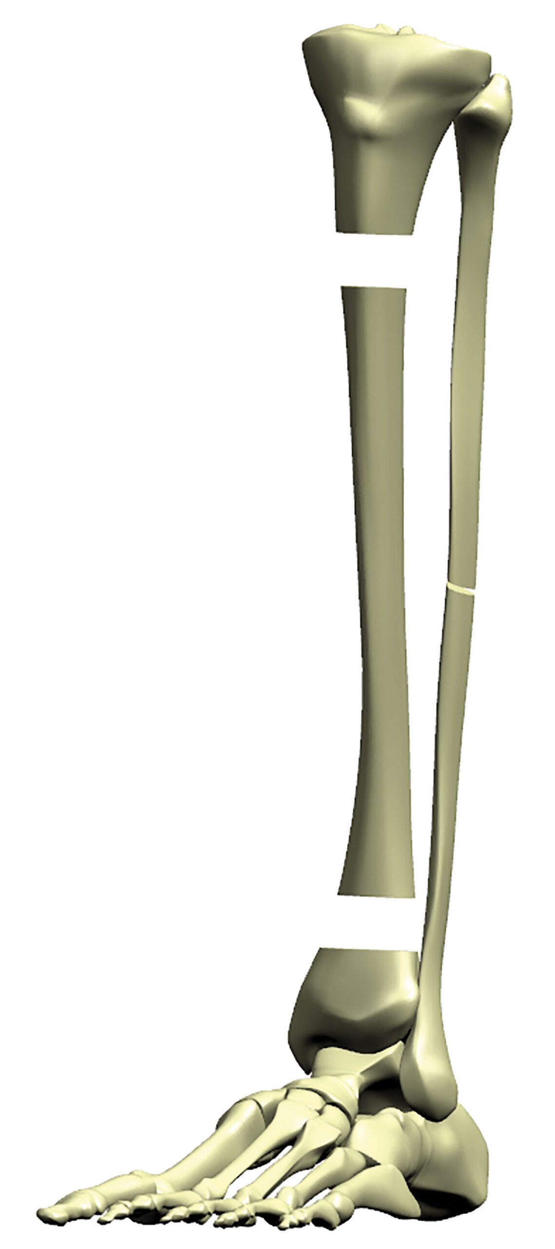
A tibial transport that involves segmental defect, and a nonunion as well as a proximal corticotomy, has three limb segments. Similarly, a proximal tibial deformity with a proximal corticotomy in association with a distal tibial nonunion also has three limb segments (Figure 2a).
The fixation for each limb segment should span the entire limb segment for maximal stability. Fixation as close to the pathology and as far away from the pathology at the ends of the segment is much more stable than all the fixation localized in the middle of the segment.
Levels of fixation
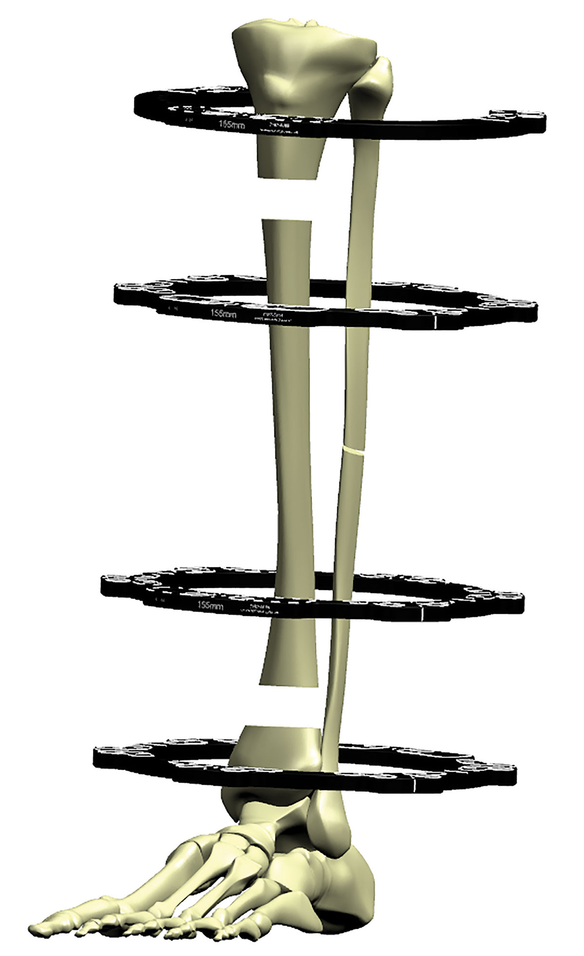
Every limb segment is usually defined by a Ring attached to that limb segment (Figure 2b). Wires or pins placed in a single axial plane is one level of fixation. This fixation is usually attached directly onto the Ring. Wires or pins that are attached above or below the Ring are designated as an additional level of fixation.
What constitutes a “stable” frame?
Tensioned wire placement
Every limb segment requires at least one level of fixation, usually a Ring positioned on each limb segment. Thus a minimum of one Ring per limb segment is required.
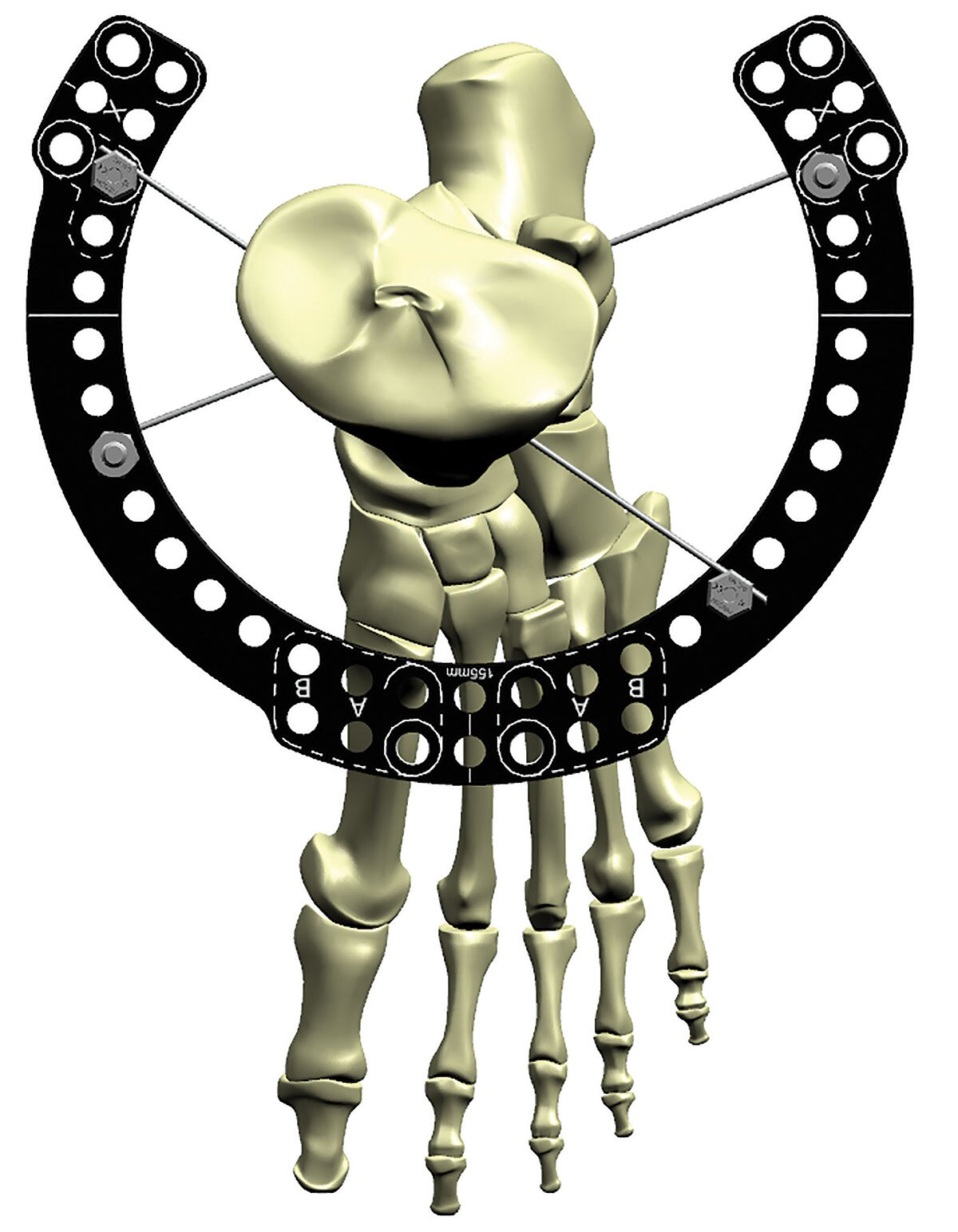
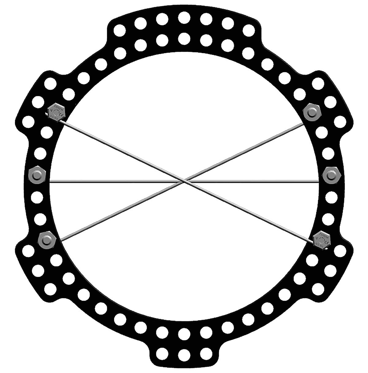
For each limb segment (Ring) the most stable construct is two tensioned wires crossing at 90° to each other (Figure 3a). This means that the wires are perpendicular to each other and would require a medial to lateral wire, as well as a wire with front to back placement. This prevents translation along the wires as well as rotational torque (bending) to the limb segment. Anatomy, however, normally precludes the ideal wire placement.

In order to avoid neurovascular structures, the wires are always placed at less than 90° but not less than a 30° crossing angle (Figure 3b).
As the wire angles converge, the potential translation along the relative combined wire axis of the limb segment becomes greater, as does the rotational torque (bending moments).
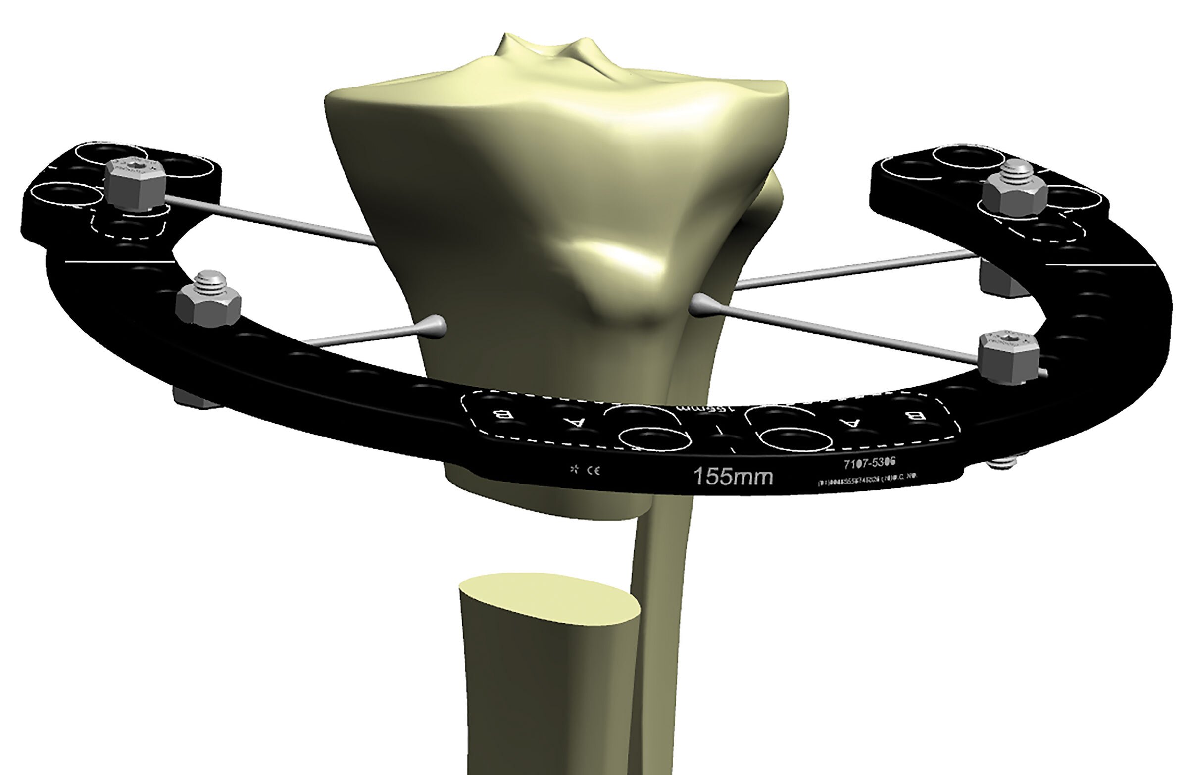
To compensate for this inability to achieve a 90° wire spread on a Ring, a third wire can be placed on the Ring. Usually you can achieve 45°- 60° of divergence between each wire and this wire orientation per limb segment is helpful but still does not achieve the optimum stability that 90°-90° achieves (Figure 3c).
Placing wires both above and below the Ring drives stability.
The addition of an Olive Wire as the third divergent wire will significantly increase the stability of the Ring segment by preventing any additional translational motion (Figure 4a).
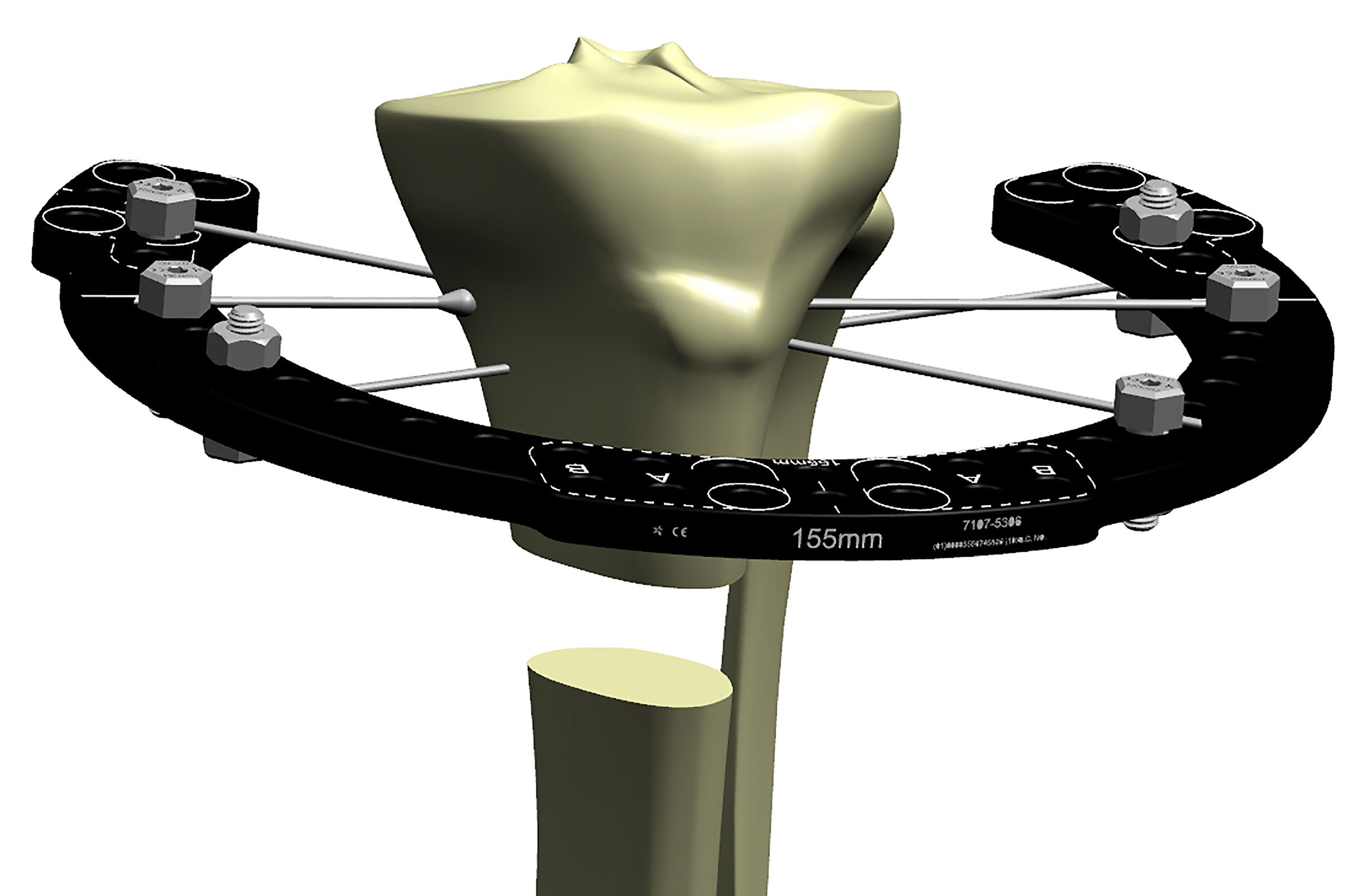
The placement of two opposing Olive Wires locks the bone into position and is a standard way to increase frame stability for that limb segment (Figure 4b).
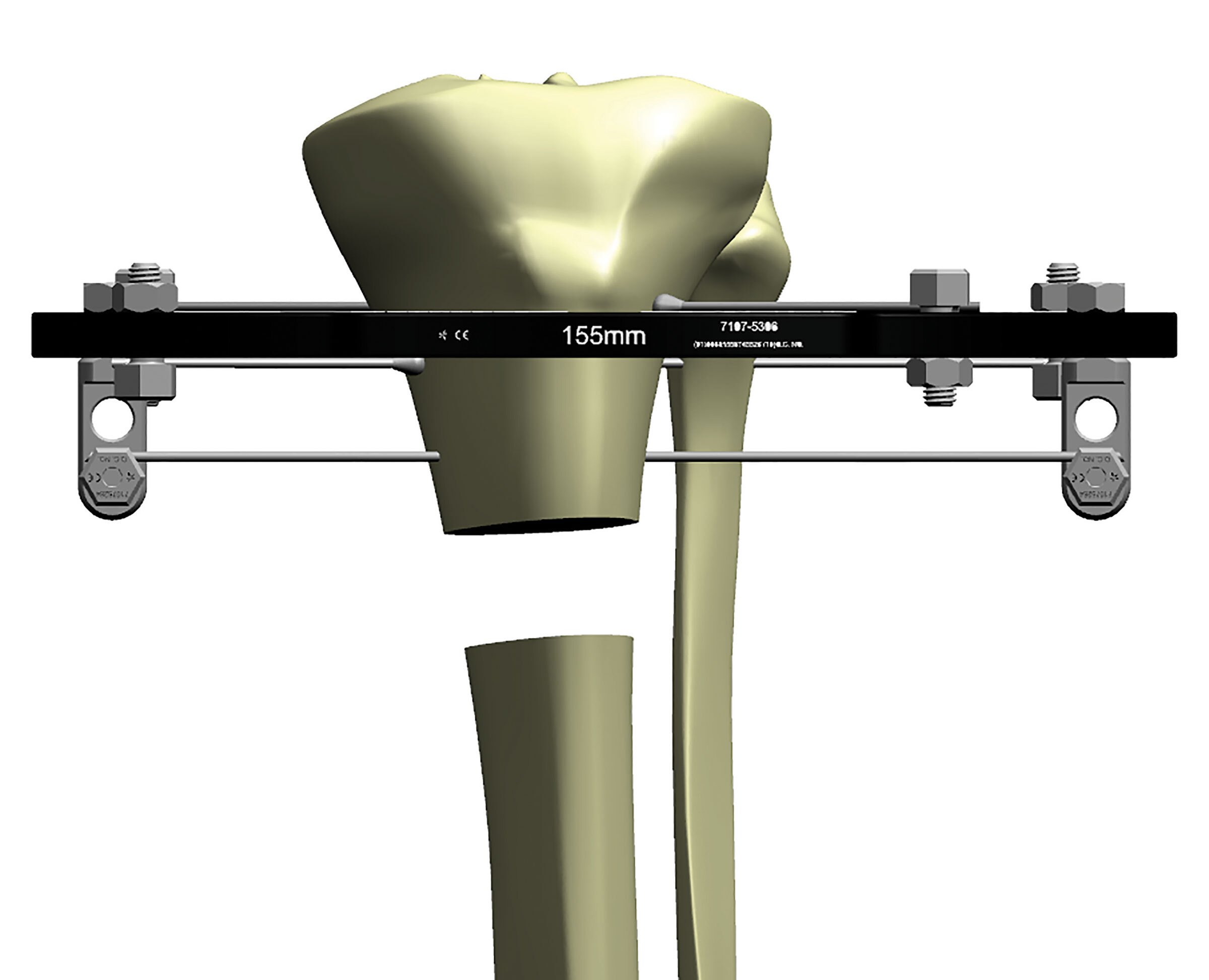
An additional level of fixation on this limb segment is still necessary. This can be achieved by adding additional tensioned wires elevated above or dropped below the Ring using posts (Figure 4c). Alternatively, placing coronal plane wires above and below the Ring, in addition to the wires placed directly on the Ring, is also a way to achieve maximal segment stability.
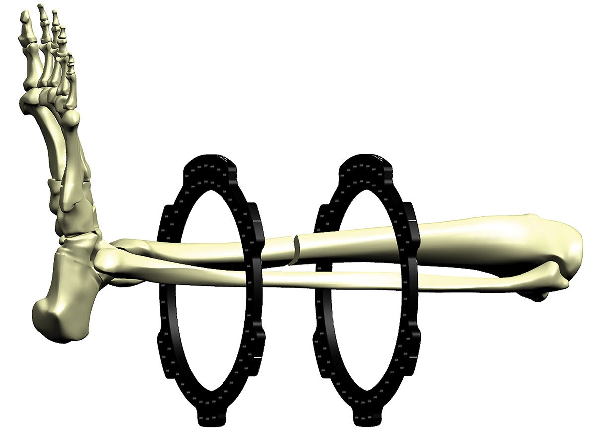
For an all-wire construct, the most stable construct is:
- two Rings per limb segment and
- two to three wires per Ring
This frame is very stable with two levels of fixation per limb segment. Divergent wires are attached to the proximal and distal Rings. A second level of fixation on each segment is accomplished by the addition of a Ring to each segment attached with two additional divergent wires. Note that none of the wires at each Ring cross at 90°; however, if the limb segment is taken as a unit looking at both Rings in that segment, the wires at different levels do achieve that 90°-90° orientation (Figure 4d). This will not always be the case because of the variable anatomy at the location of the segment and thus the need for half pin augmentation.
Half Pins
The use of an additional Ring is often not feasible due to available room needed for an additional Ring. Thus the ability to add another level of fixation above or below the Ring is achieved by using a half pin (often called Schanz Pin) (Figure 5a).
While two wires placed in 90°-90° configuration is the target for optimal stability, most frames utilize half pins as a strategy to increase stability without the constraint of available wire corridors.
In terms of comparable stability, two half pins placed on the same level with 30°-45° of pin divergence is equivalent to one tensioned wire (Figure 5b). A stable limb segment then can consist of two tensioned wires mounted on the Ring with two additional half pins mounted above and/or below the Ring. Each pin is placed through divergent (non-orthogonal) orientation. This formula achieves two levels of fixation per limb segment and the pin/wire trajectories achieve the desired equivalency of a 90°-90° tensioned wire frame.
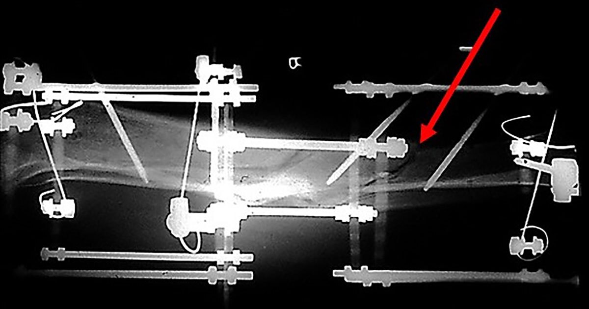
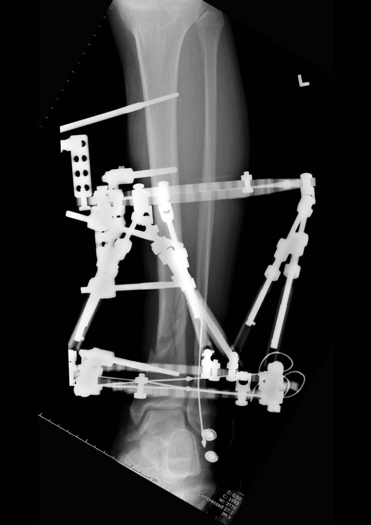
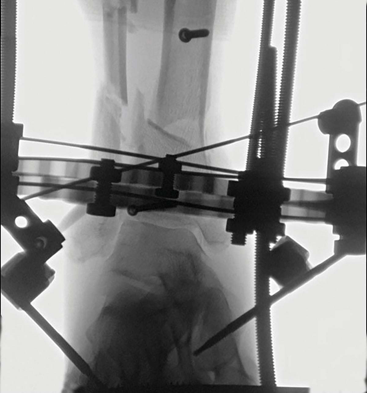
Figure 6 shows a hypertrophic nonunion which is very stiff and requires a very stable frame to affect a slow correction. It has two limb segments with two levels of fixation per limb segment. The distal limb segment below the nonunion is stabilized with two opposing Olive Wires mounted directly onto the distal Ring with two additional half pins elevated off the Ring and placed in 80° divergence (two Olive Wires and two half pins equals one additional wire) (Figure 6).

The proximal limb segment has two levels of fixation with the fixation spanning the entire limb segment using two Rings. Each Ring has two widely divergent half pins achieving the equivalent stability of two 90°-90° tensioned wires. This is a very stable frame and achieves excellent correction and complete healing of this hypertrophic nonunion with exuberant callus.
Full half pin frames can also be used successfully and with equivalent mechanical stability by placing three 60° divergent 6mm half pins above and below a Ring spanning the entire length of the limb segment (Figure 7a).
A similar second Ring with divergent pins above and below the Ring is also placed. This six-pin frame with divergent 6mm half pins is equivalent to a four-Ring tensioned wire frame in terms of axial stability and bending resistance while allowing axial micromotion (Figure 7b).
The addition of out-of-plane half pins to any limb segment produces a significant increase in stability to that particular limb segment and should be utilized when a very rigid frame is indicated, such as for deformity, lengthening or nonunion treatment.
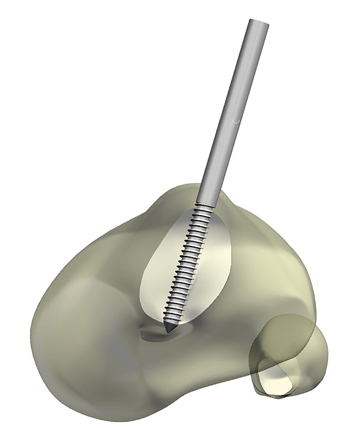
Steerage Pins
The addition of half pins can increase the compressive forces across a fracture line and increase the overall stability of a fracture frame. The pins should be placed parallel to their respective fracture line orientation (Figure 8a). With fracture loading, the resultant motion vectors of both limb segments serve to force them together in a compression mode. The pins have to be located on each separate limb segment in order for this compression vector to work.
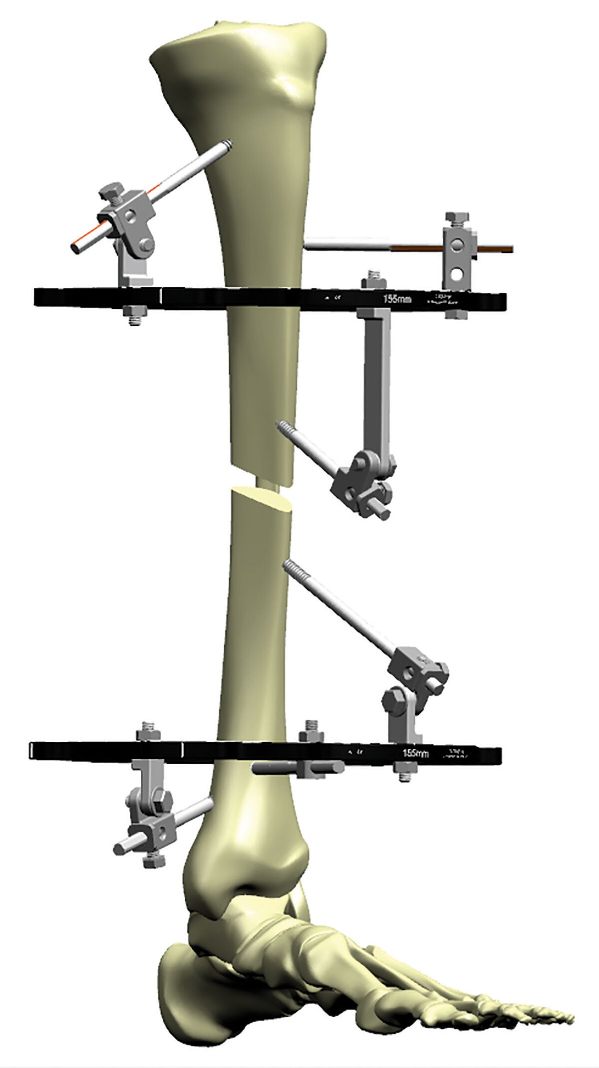
Note that two half pins are each located in a separate limb segment, each on separate Rings. One above the oblique fracture line and the second below the fracture line, both positioned parallel to the orientation of that oblique fracture line. This pin placement will convert the normal cantilever shear forces that want to distract the fracture to a resultant compressive force. The result is an increase in frame stability and fracture fragment contact (Figure 8b).
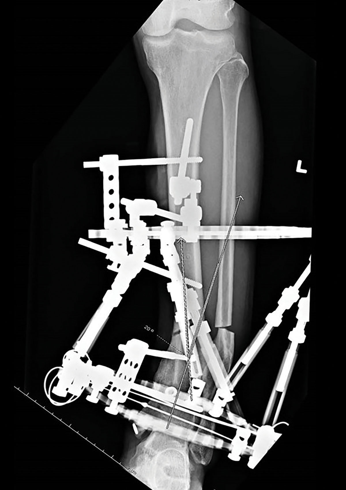
Hypertrophic nonunion with two limb segments and one Ring per each limb segment.
The widely divergent 6mm half pins are placed above and below the Ring in at least 60° of divergence in all three planes, achieving two levels of fixation per segment.
This stable frame demonstrates a wide divergent pin spread covering the entirety of each limb segment, while providing at least two levels of fixation per limb segment (Figure 9).
Example – Malunion with varus deformity
with a corticotomy
Two limb segments with one Ring per segment. Distal Ring fixation using two divergent wires and an Olive Wire on the Ring and an additional half pin placed above the Ring, achieving two levels of fixation in that limb segment. The proximal limb segment is stabilized by a single Ring with four divergent half pins placed above and below the Ring to achieve a wide area of proximal segment fixation (Figure 10a).
Example – Two limb segment pilon fracture
The distal segment is stabilized with three tensioned wires including two Olive Wires and an additional half pin placed above the Ring for two levels of fixation. Proximal limb segment with single Ring and four divergent half pins placed above and below the Ring again achieve two levels of fixation for this limb segment (Figure 10b).
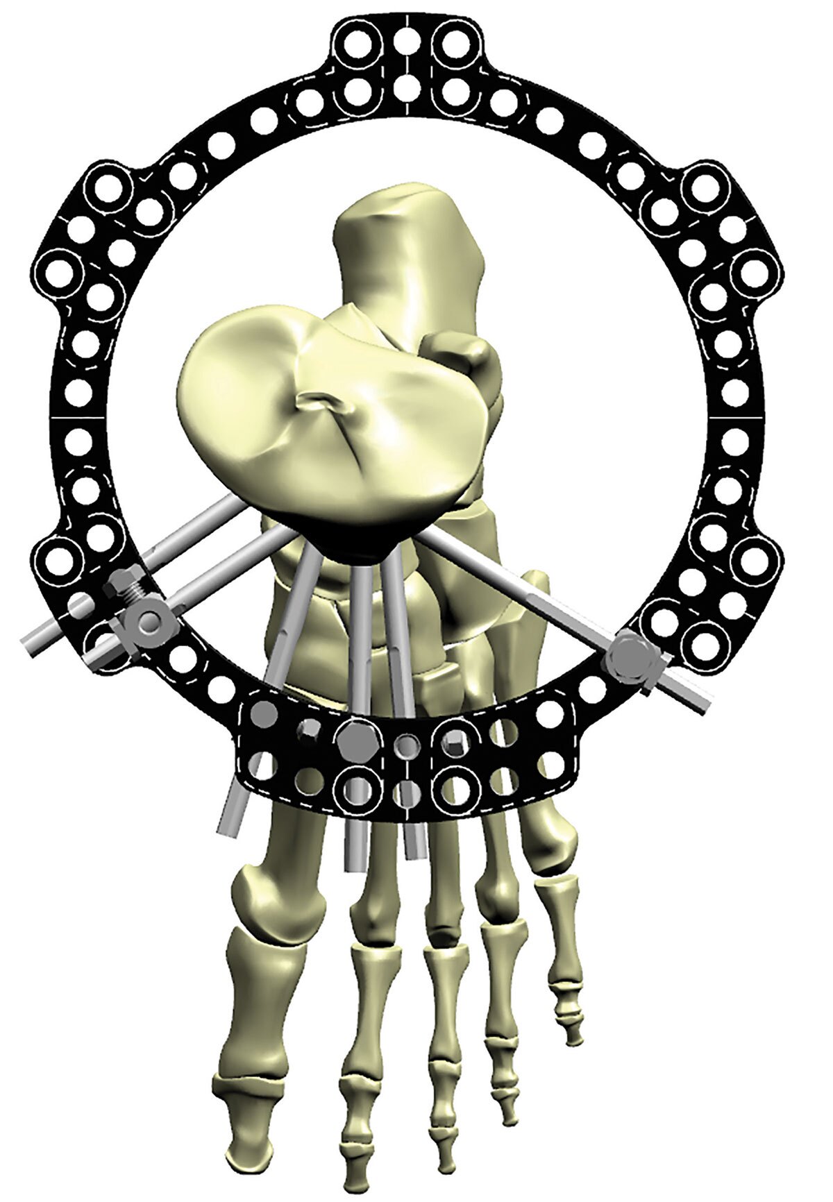
Example – Short periarticular segment
Additional stability of a short distal limb segment can be achieved with out-of-plane tensioned wires. Note the wires in the coronal plane that course above the Ring on one side and below the Ring on the opposite side (Figure 10c). This configuration again confers two levels of fixation for this small limb segment.
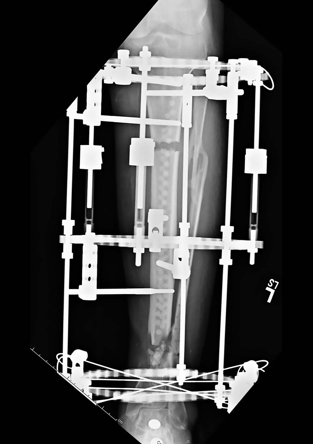
Bone transport constructs require the ability to vary the biomechanics as treatment progresses (Figure 11). The top limb segment should be constrained and attached to the distal limb segment. In this fashion the unstable transport segment can depart to eventually dock with a stable limb segment.
Less constrained frames risk the development of inadequate regenerate and nonunion at the docking site because of the inherent instability. Note the long Threaded Rods connecting the proximal limb segment to the distal limb segment and thus avoiding construct instability. The proximal Ring fixation demonstrates two levels of fixation with three divergent half pins and smooth wires. Distal limb segment fixation of the small segment is accomplished with five tensioned wires and two coronal plane wires attached above and below the distal Ring for two levels of fixation.
The intercalary transport Ring is mobile along the long Threaded Rods and thus the docking site will be in perfect alignment as docking occurs. The transport Ring segment is stabilized with a Ring and half pins above and below the Ring. Note that the majority of fixation is located distally on the transport segment. This fixation “pulls” the segment distally and is much more stable, controllable and facilitates docking by being able to compress symmetrically at the docking site. When fixation is more proximal above the transport Ring, this is very unstable and the transport segment will drift with distraction. It is much easier to “pull” a string of spaghetti rather than push it!
Factors that increase frame stability size of Rings
It is important to use Rings that are not excessively large. Rings with large diameters place the fixation points far away from the point of contact to bone and the fixation is prone to excessive cantilever, bending and potential shearing of the pin or wire. Decreasing Ring size also helps to increase axial stability. Increasing the number of Ring-to-Ring connections between limb segments also improves frame stability, especially in large patients that require large Rings (Figure 12a).
Pin and wire diameter
Increasing pin and wire diameter improves the resistance to bending and torsion as well as improving axial stability (Figure 12b). Wires tensioned appropriately and tensioned to the correct level increases the axial stability of the frame. Use of Olive Wires as previously noted adds resistance to translation and bending.
Pin diameter does not exceed 1/3 diameter of bone
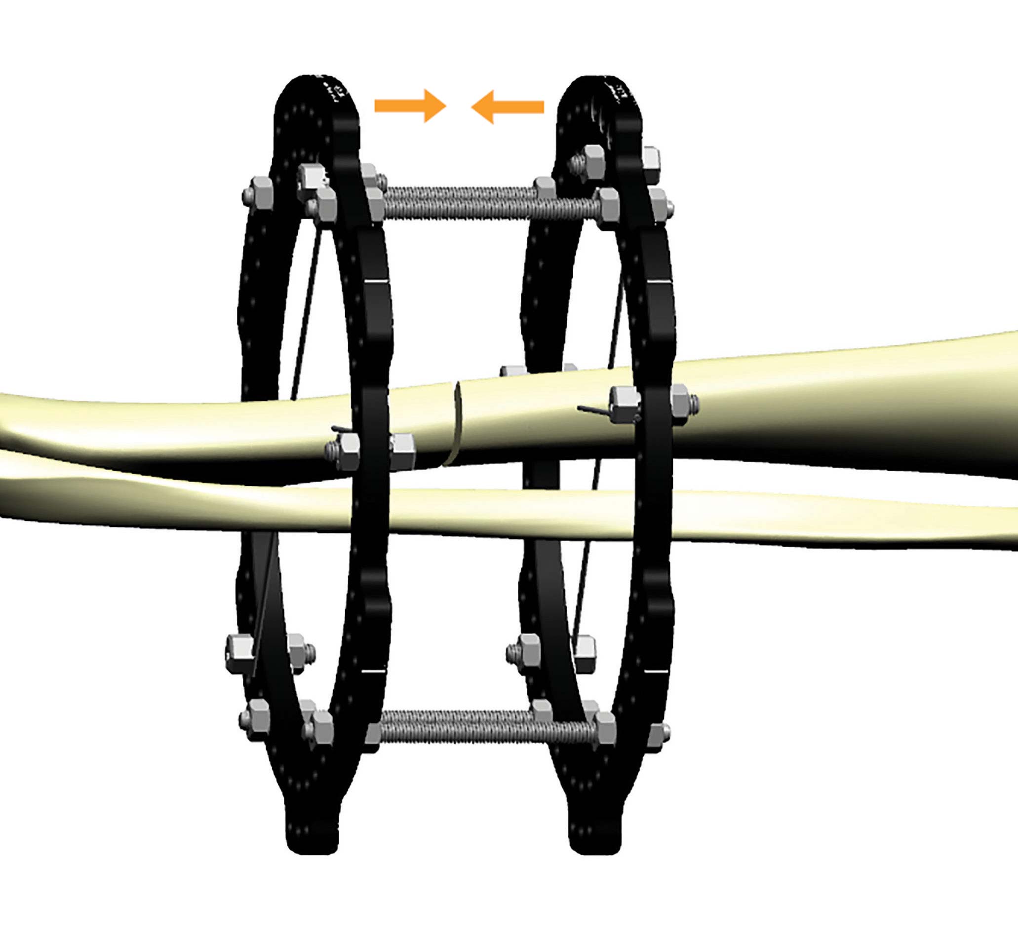
Counter Ring compression
Tightening or compressing the Rings toward each other where two Rings are used in a limb segment or on either side of a fracture serves to increase the wire deflection on each Ring and subsequently increases the wire stiffness (Figure 12c). This self-stiffening effect has the same impact as re-tensioning the wires and improves frame stability and decreases the pain that an unstable frame will cause.
Suggested Videos