Use of COMPASS◇ Universal Hinge with Circular Fixation
B. J Ollivere, MBBS, FRCS, MD; University of Nottingham, UK
The views and opinions expressed in this section are those of the surgeon.
Introduction
COMPASS Universal Hinge is a versatile device in complex trauma and degenerative situations. The design allows flexibility of application to the knee, elbow and ankle.
Articulated circular fixators using COMPASS Universal Hinge are helpful to address complex fracture dislocations where:
- Ligaments are unreconstructible
- Bony architecture cannot be restored to achieve stability
- Immediate weight-bearing or range of motion is required
There are also some situations in post-traumatic or degenerative conditions where COMPASS Universal Hinge can be used to either provide gradual stretching via the worm gear, or as an articulated distractor in, for example:
- Post-traumatic stiffness
- Joint distraction for arthrosis
Whilst useful in post-traumatic stiffness it is important to remember that few joints are completely concentric, and as such COMPASS Universal Hinge is only helpful in those cases where it can either be combined with soft tissue releases to achieve a good range of motion, or those in which soft tissue releases are impossible, and a smaller range of motion is to be accepted.
Operative tactic
Application of COMPASS Universal Hinge requires meticulous planning. The hinge must be applied so that:
- The centre of rotation of the device is positioned as closely to that of the joint as possible
- Each articulating side connects to a 2/3 Ring
- Half pins are used to maximise stability of the construct
- Minimal muscle tethering occurs
When planning an articulated frame it is sensible to sequence the approach such that:
- The centre of rotation is found first with a wire to guide placement
- Ring size selection optimizes the tolerances on centre of rotation
- The correction orientation for range of motion is established (elbow: gear placed medially with dial posterior; knee: dial is posterior, ankle: dial is anterior)
- Mounting is usually easier to achieve first in the tibia for lower extremity application, and humerus for upper extremity
- When building constructs to support trauma (eg plateau fractures with bone loss) ensure the proximal Ring is positioned to allow space for COMPASS Universal Hinge. Extend fixation with Ring blocks in complex fracture situations. This step should be undertaken first as part of mounting the trauma frame
- COMPASS Universal Hinge can be mounted to internally facing Step-off Plates if positioning is tricky
- Varus/valgus adjustments are easily accomplished with the 20˚ arc of allowable motion, however, should not be forced and all connections to the frame should be loosened prior to final corrections
Matching axes of rotation
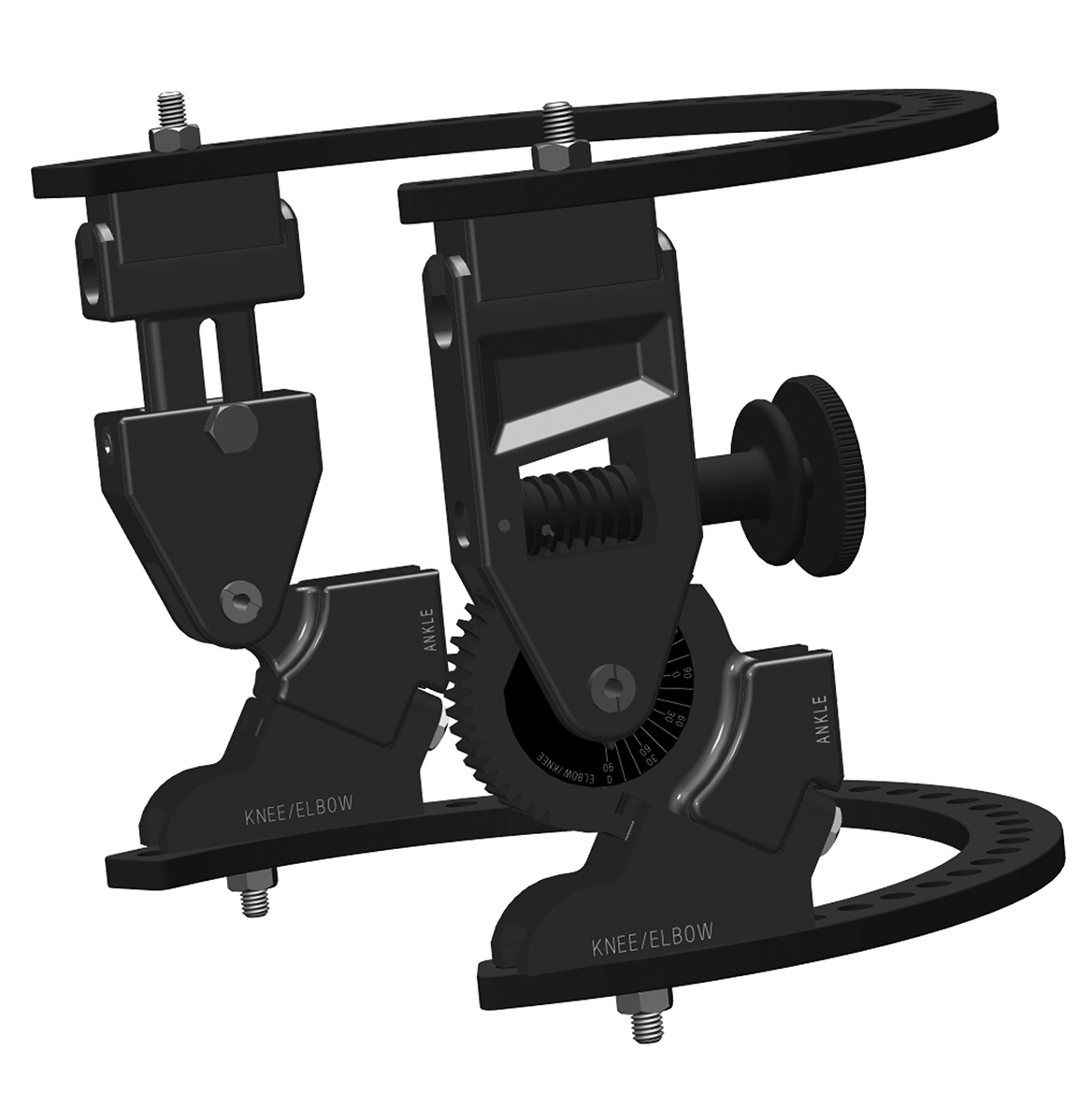
The COMPASS Universal Hinge is designed to align its mechanical axis with the anatomic axis of the joint – elbow, knee or ankle. This allows the hinge to work with the joint, moving it through a biomechanically normal range of motion. A choice of passive or active modes are designed to ensure the greatest therapeutic value for each individual patient. As with the original design, radiolucent construction assists with the alignment of the axes during hinge application. Once the hinge is placed, the axis reference wire is removed to reduce the likelihood of infection in the joint capsule.
Versatility
The COMPASS Universal Hinge offers great versatility for use on the elbow, the knee or the ankle and requires only a few simple adjustments for any application.
Precision worm gear
The COMPASS Universal Hinge incorporates a precision worm gear that is designed to provide controlled displacement throughout the extremes of flexion and extension.
Range of valgus
The self-telescoping design of the COMPASS Universal Hinge allows a full range of 10° varus to 10° of valgus, allowing anatomically appropriate application to the elbow, knee or ankle.
Radiolucent arcs
Allow X-ray visualization of the anatomy.
CORK Axis Wire
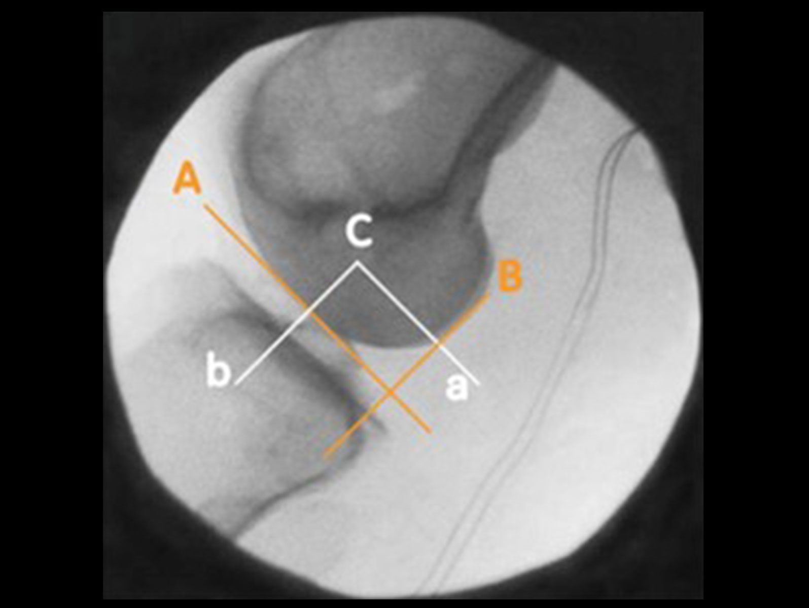
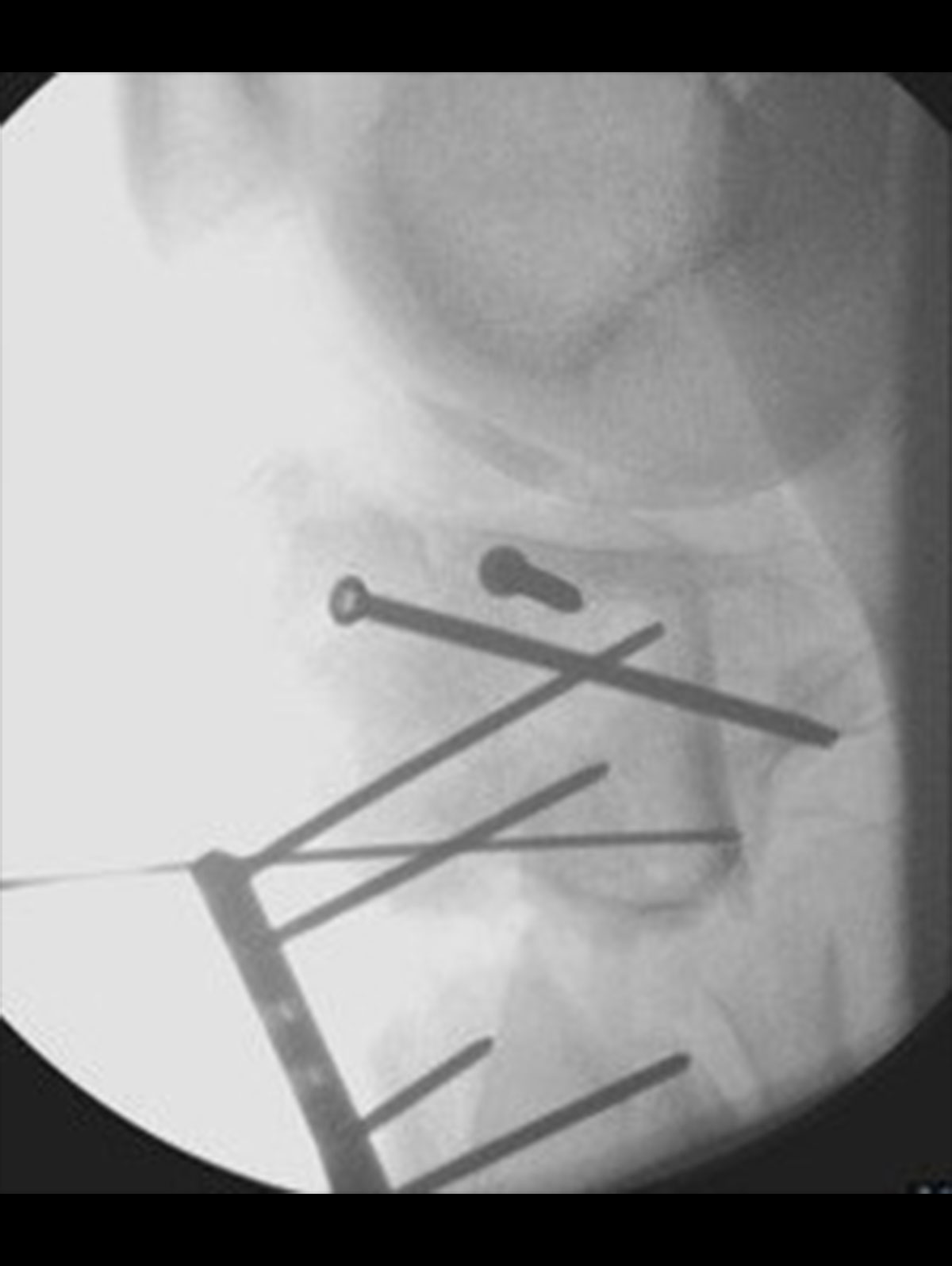
The centre of rotation of Knee should be identified on the lateral view with a smooth wire (Figure 4).
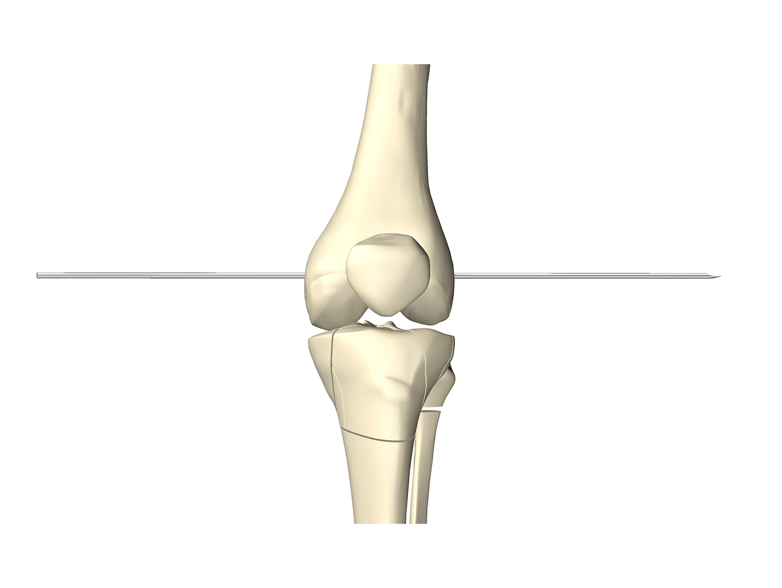
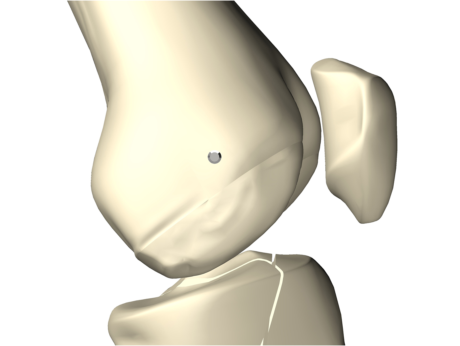
Figure 4
A = Distal femoral line
B = Posterior femoral line
a = Line parallel to A, bisecting B at most posterior point of condyles
b = Line parallel to B, bisecting A at most distal point of condyles
C = Center of rotation
C is the point where a and b intersect
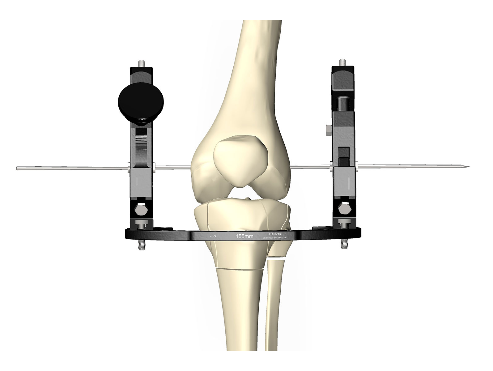
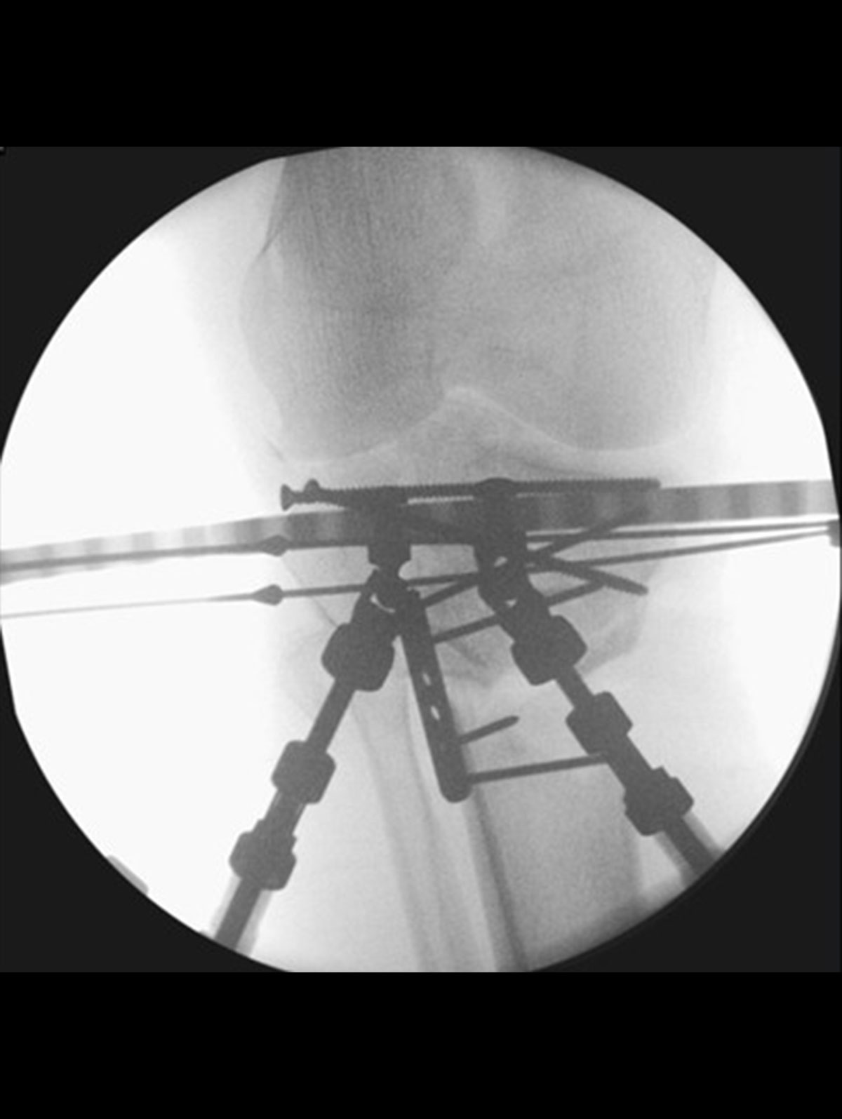
Mount the distal Ring/Ring block first, as this will be utilised to both fix the fracture and stabilise the knee axis. In order to do this effectively the COMPASS Universal Hinge components should be positioned first, and the Ring mounted on the COMPASS Universal Hinge components without bending the CORK Wire (Figure 5).
Tibial Ring
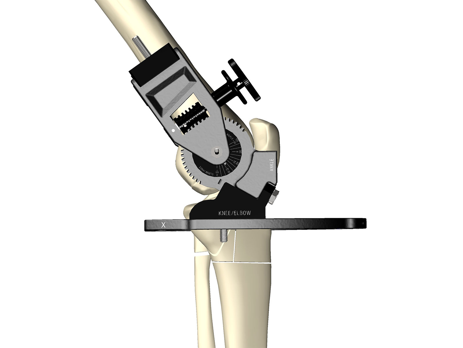
Once the Ring is mounted appropriately and parallel to the tibial plateau the rotation position can be checked in the lateral view (Figure 6).
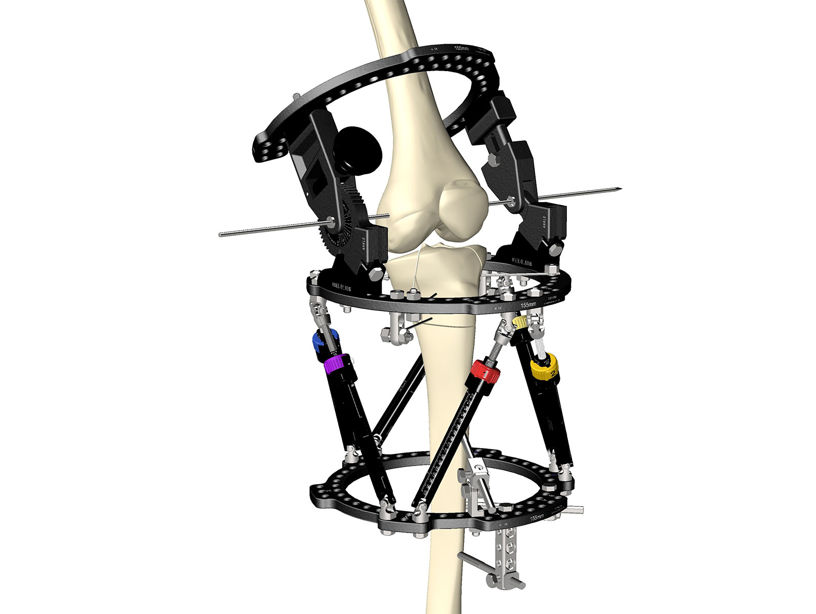
The next step varies depending on fracture pattern, but it is preferable to complete the fracture fixation at this point, which would be completed as for any fracture with reduction, percutaneous lag screws if needed and a bridging frame (Figure 7).
Fracture Fixation
Femoral Ring
Finally mount the femoral side of the COMPASS Universal Hinge at this point. It is essential to check the axis again to ensure it is correct, and utilise the length-adjustable lateral hinge component to ensure the femoral Ring can be aligned to the axis of the femur.
The tibial Ring should be positioned as anterior as possible to allow range of motion (Figure 8 and Figure 9).
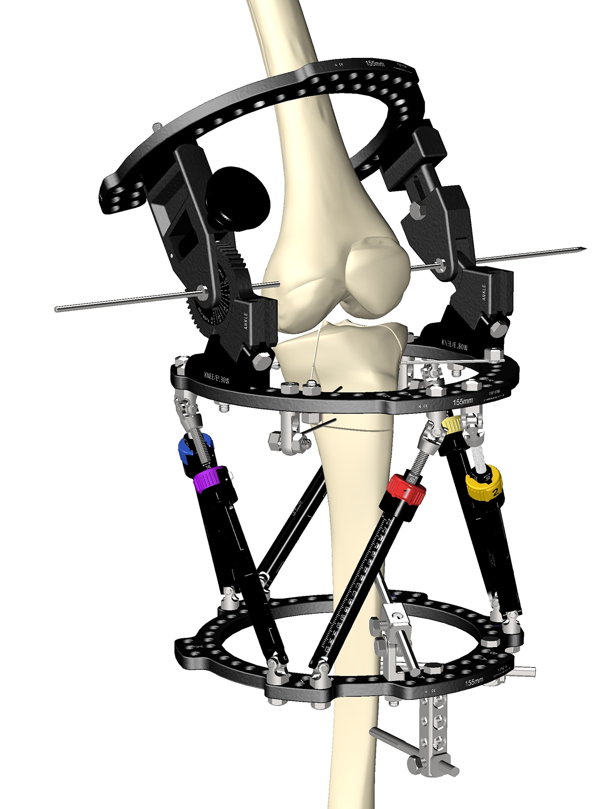
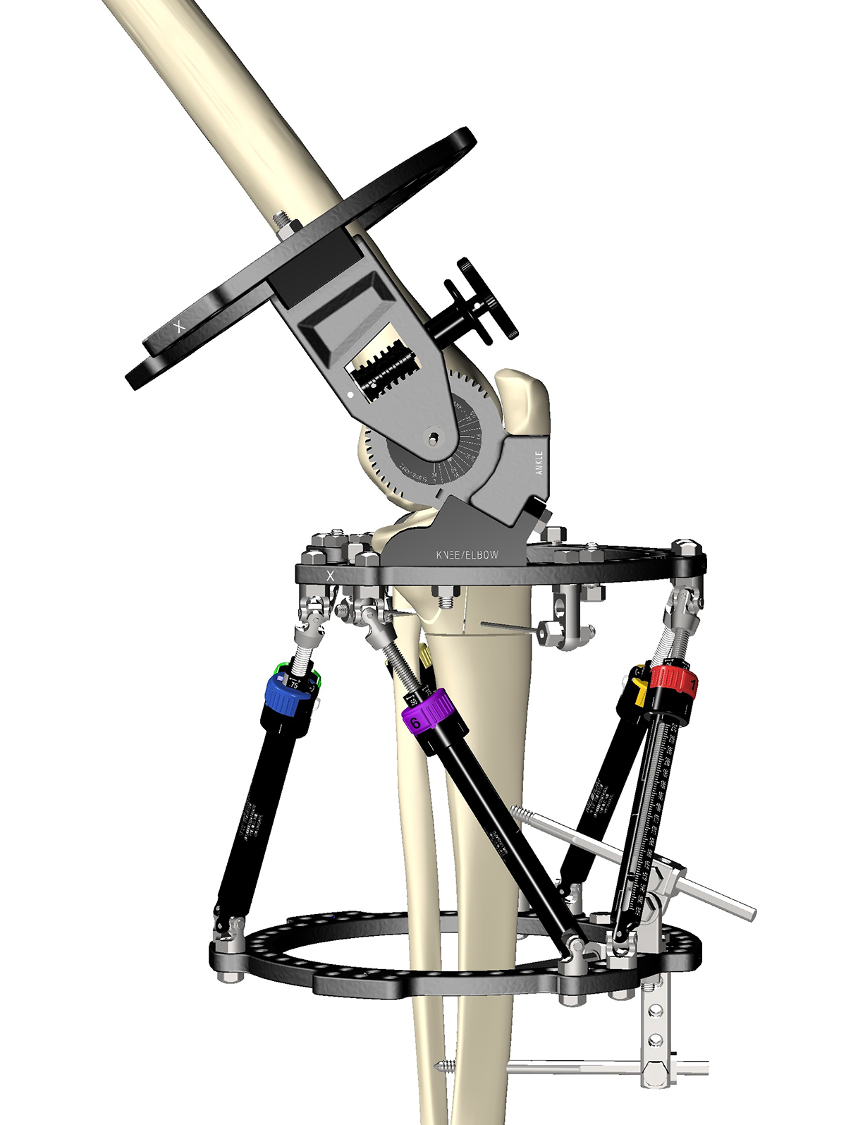
Figure 10
COMPASS Universal Hinge attachment is easiest with approximately 15˚ of flexion at the knee. The image shows how towels or padding serve as a cushion under the Ring. The tibial Ring should be positioned as anterior as possible to allow range of motion.
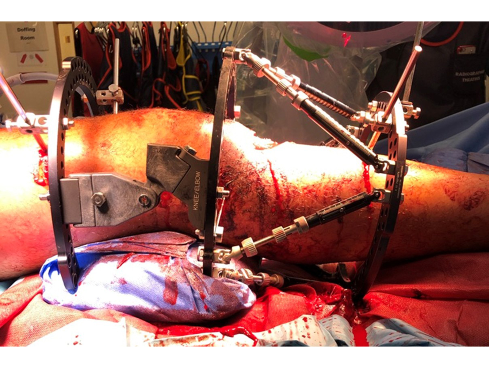
Fix the Femoral Ring
A single proximal Ring is usually sufficient. Ensure adequate Pin spread along the para-vastus corridor.
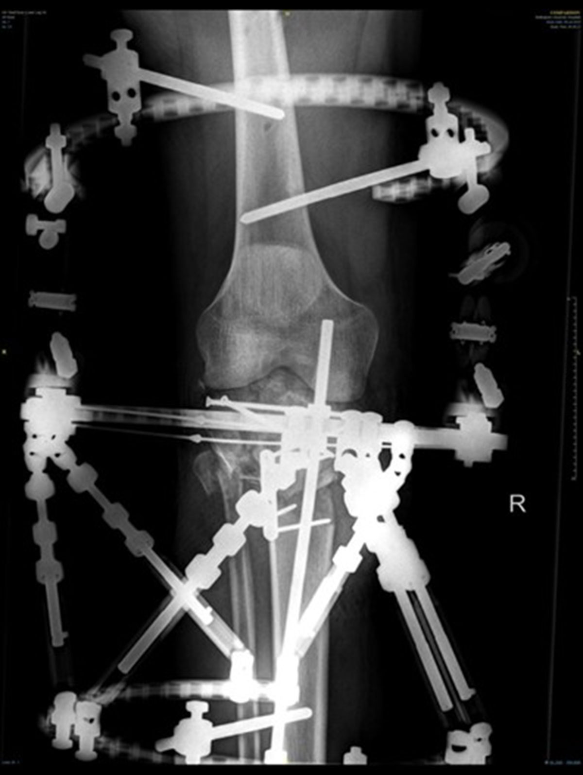
Final assembly (Figure 11 and 12).
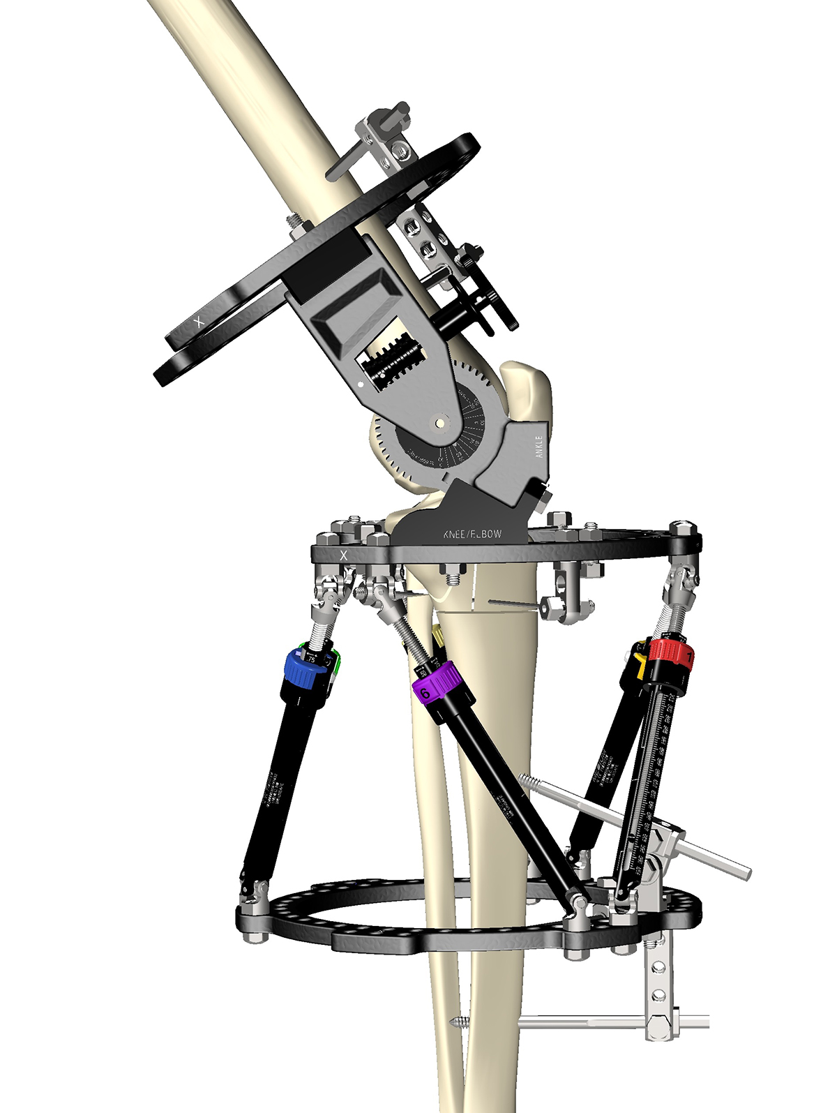
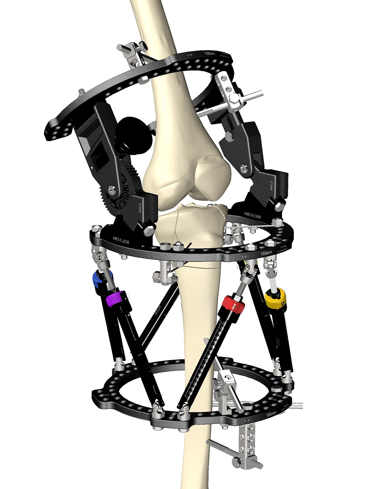
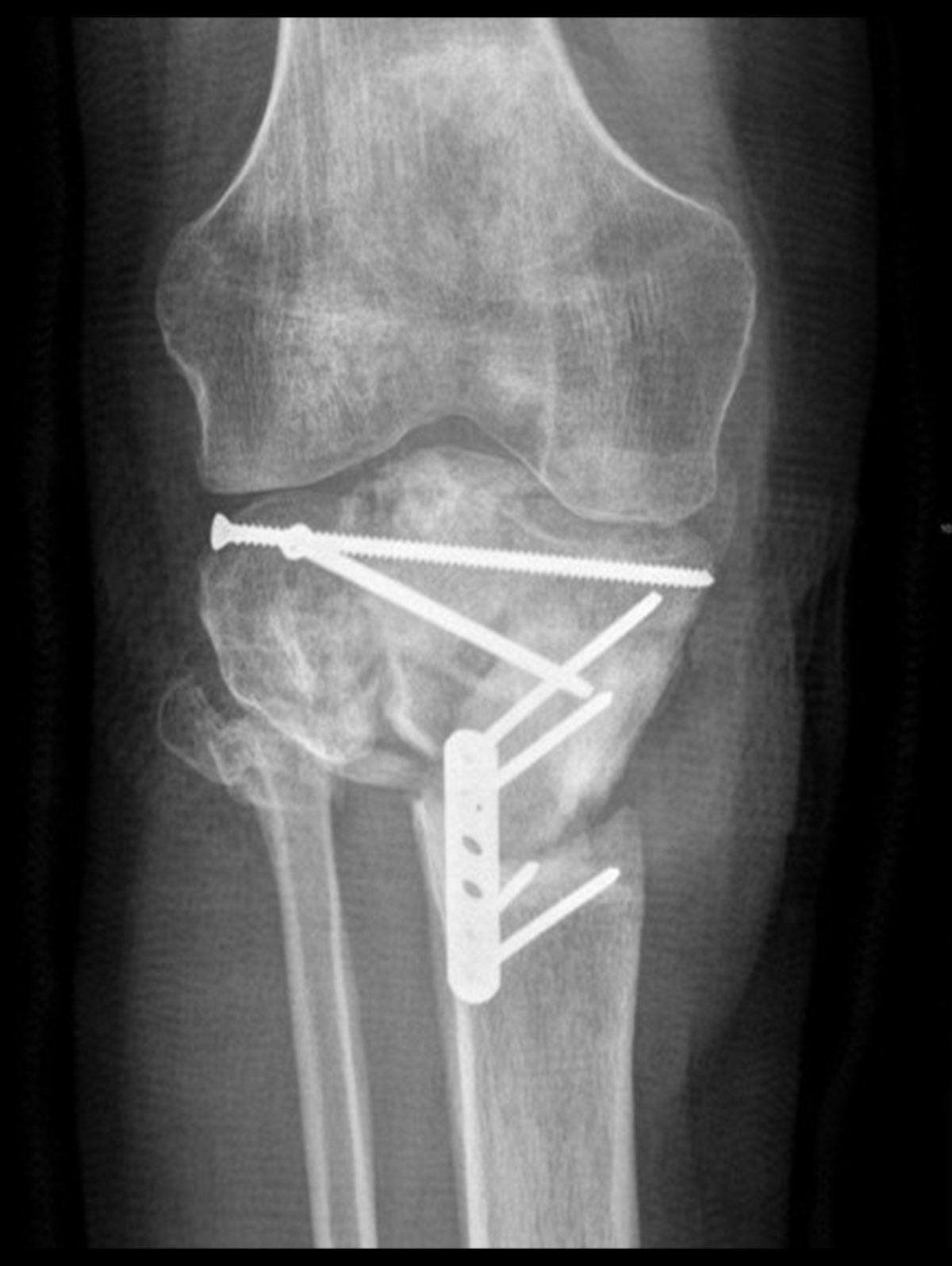
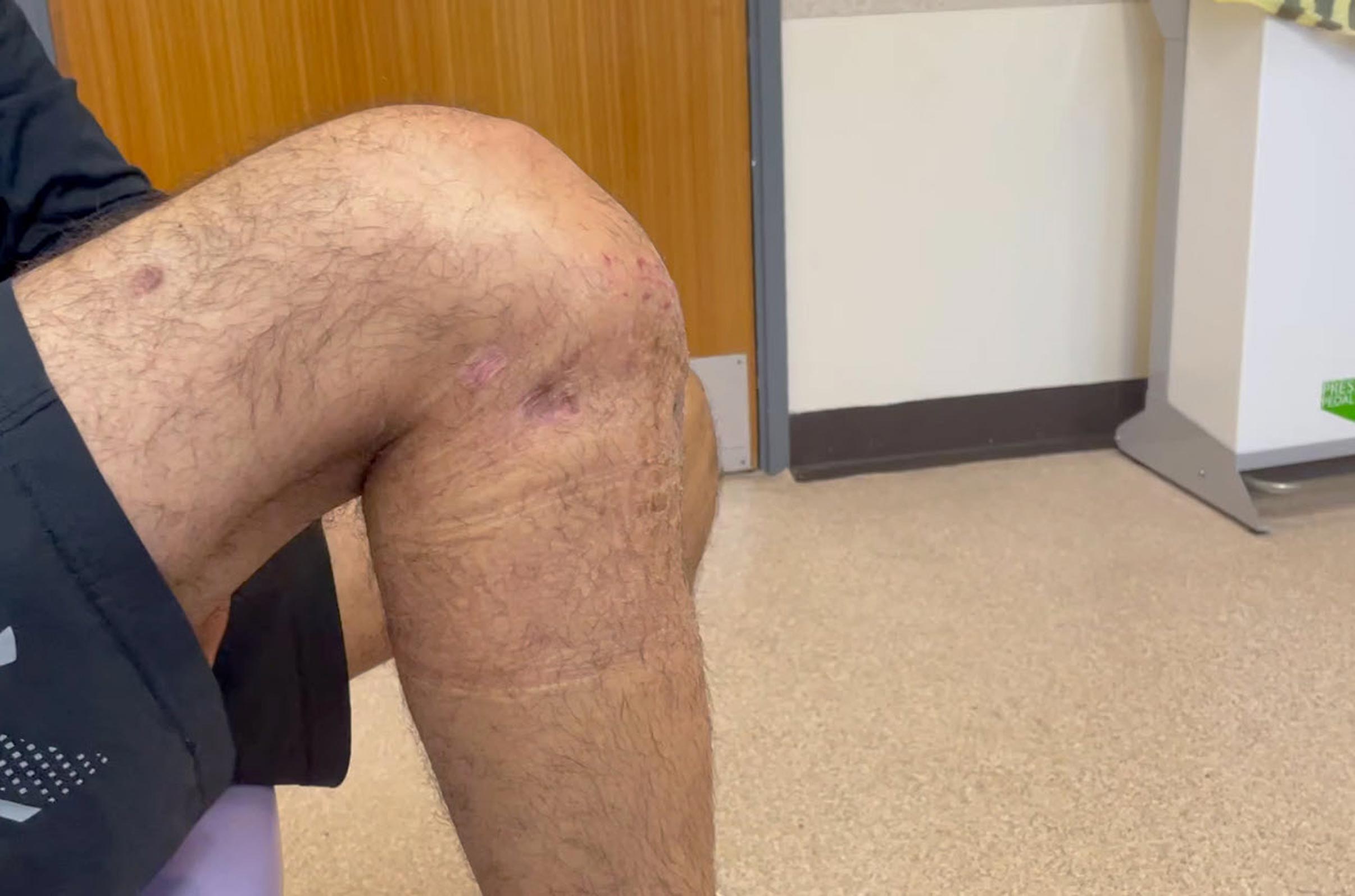
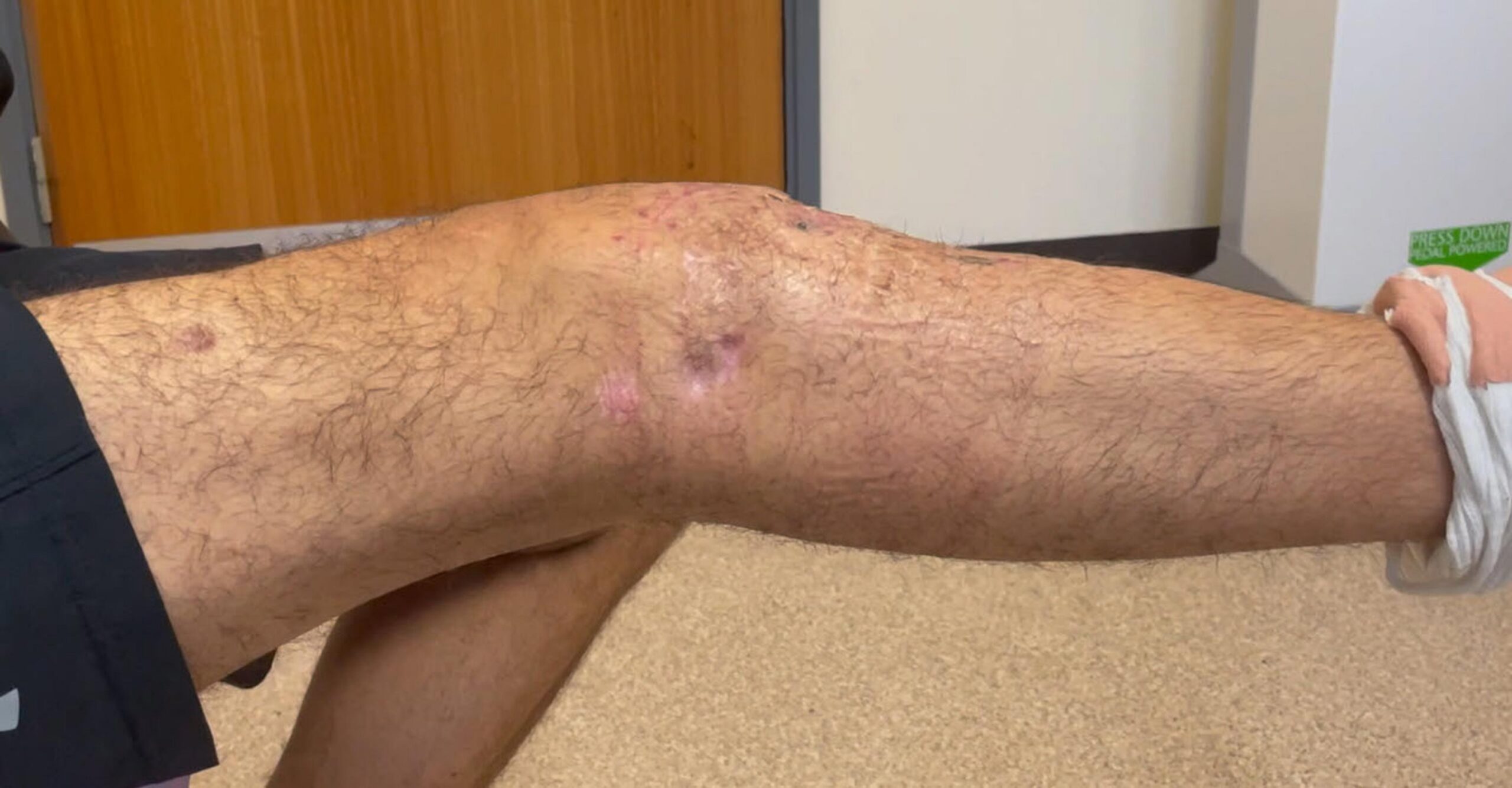
Case Example – Knee
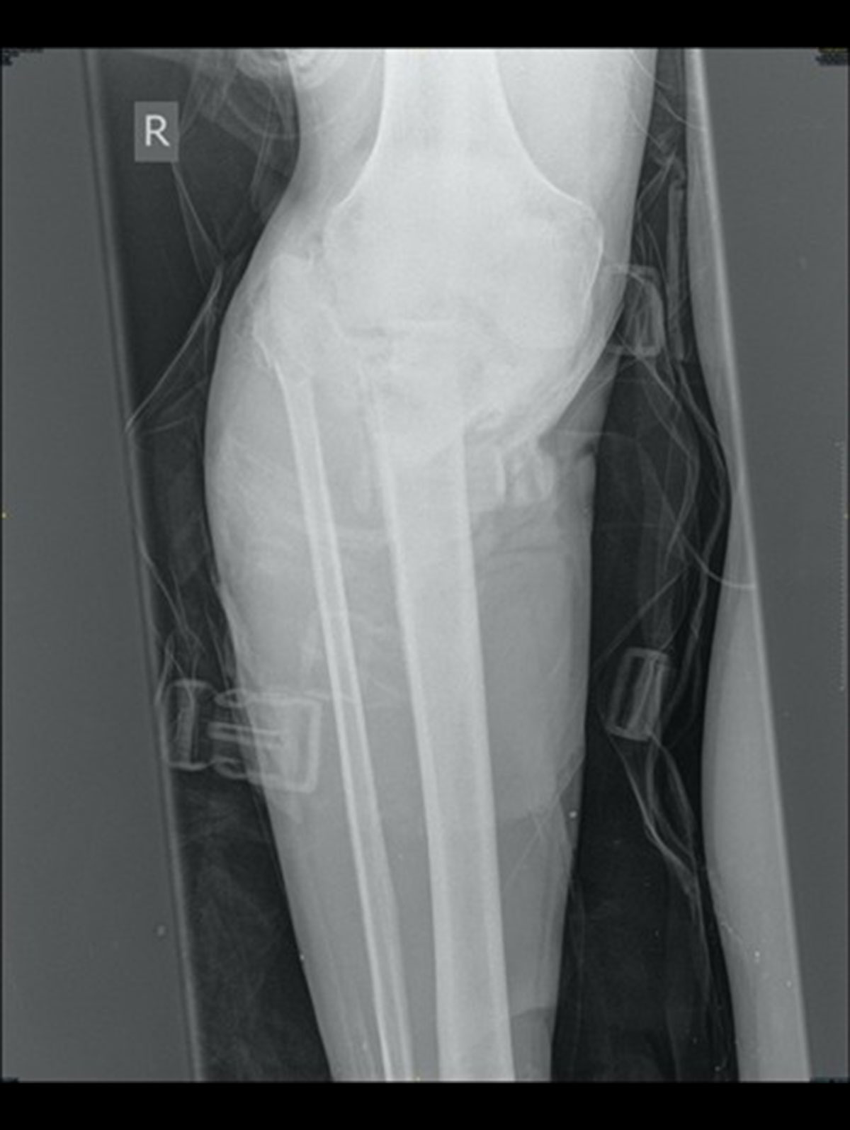
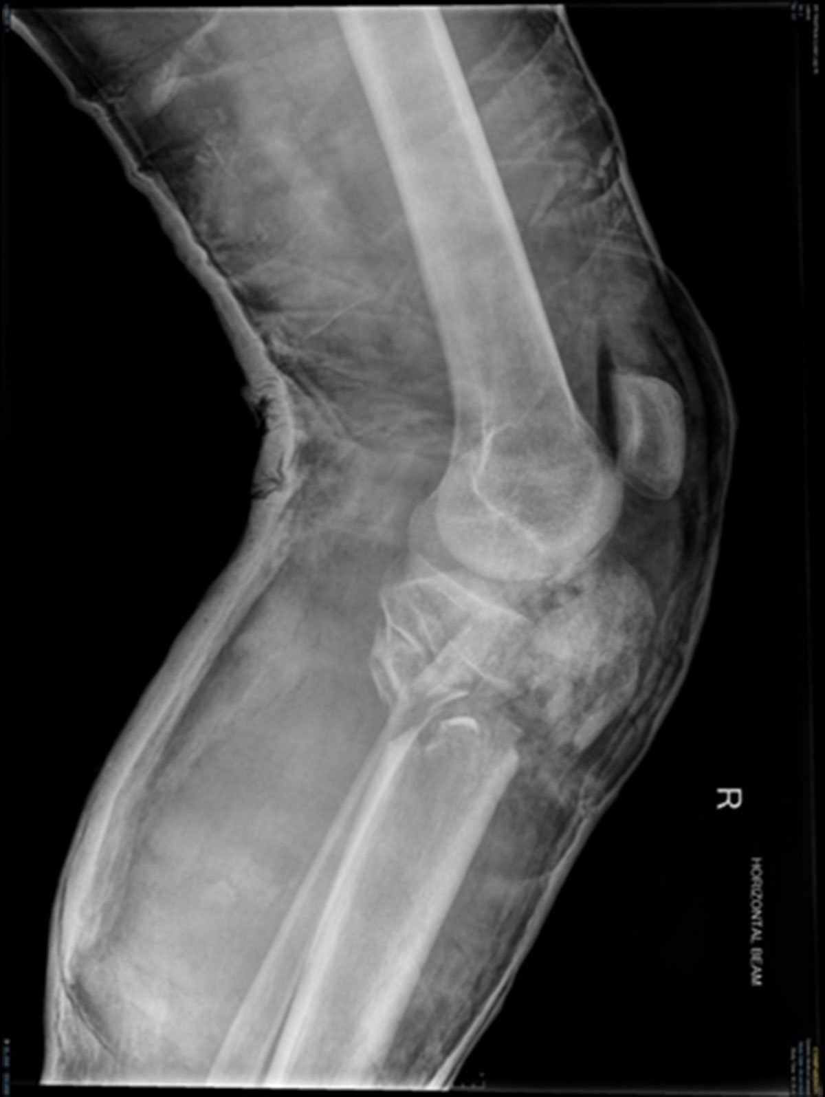
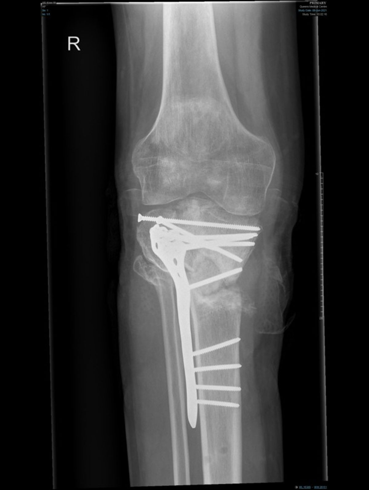
23 year old male comes off his motorcross bike on a jump at speed. Open fracture to the tibial plateau with significant loss of soft tissues and combined ligamentous injury. Neurovascular supply is intact and surgery is undertaken.
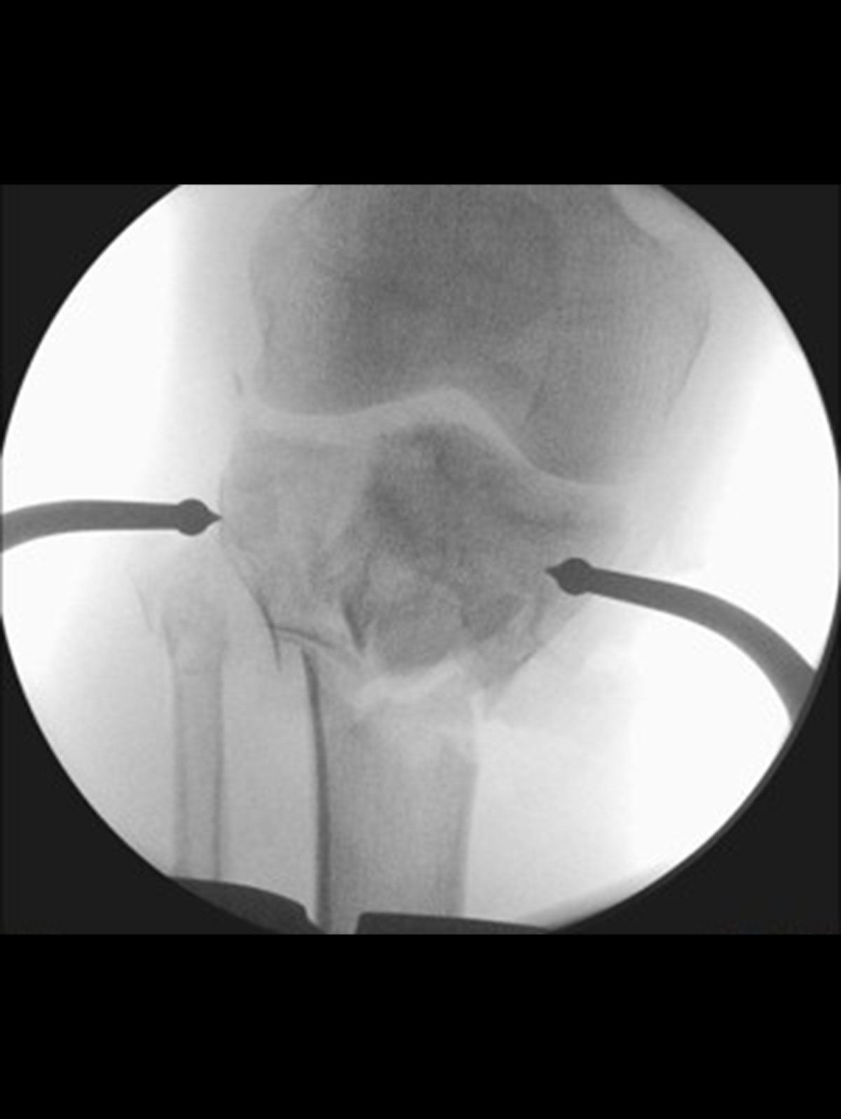
Application of COMPASS Universal Hinge to the Elbow
Introduction
Around the elbow, COMPASS Universal Hinge is typically applied for soft tissue indications. It can be used to address complex fracture dislocations where:
- Ligaments are unreconstructible
- Bony architecture cannot be restored to achieve stability
- Post traumatic stiffness requiring use of articulated stretching
- Joint distraction for arthrosis
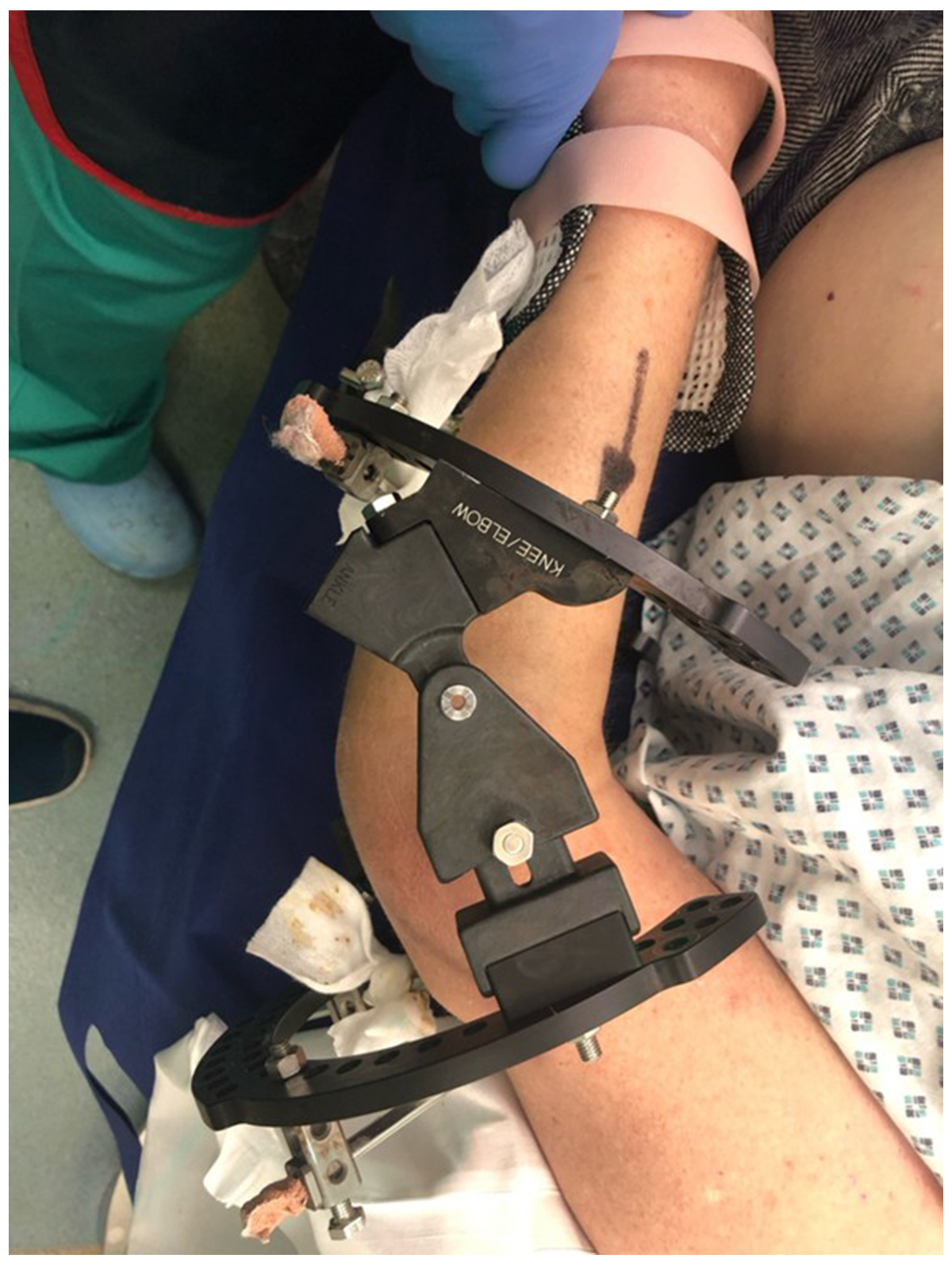
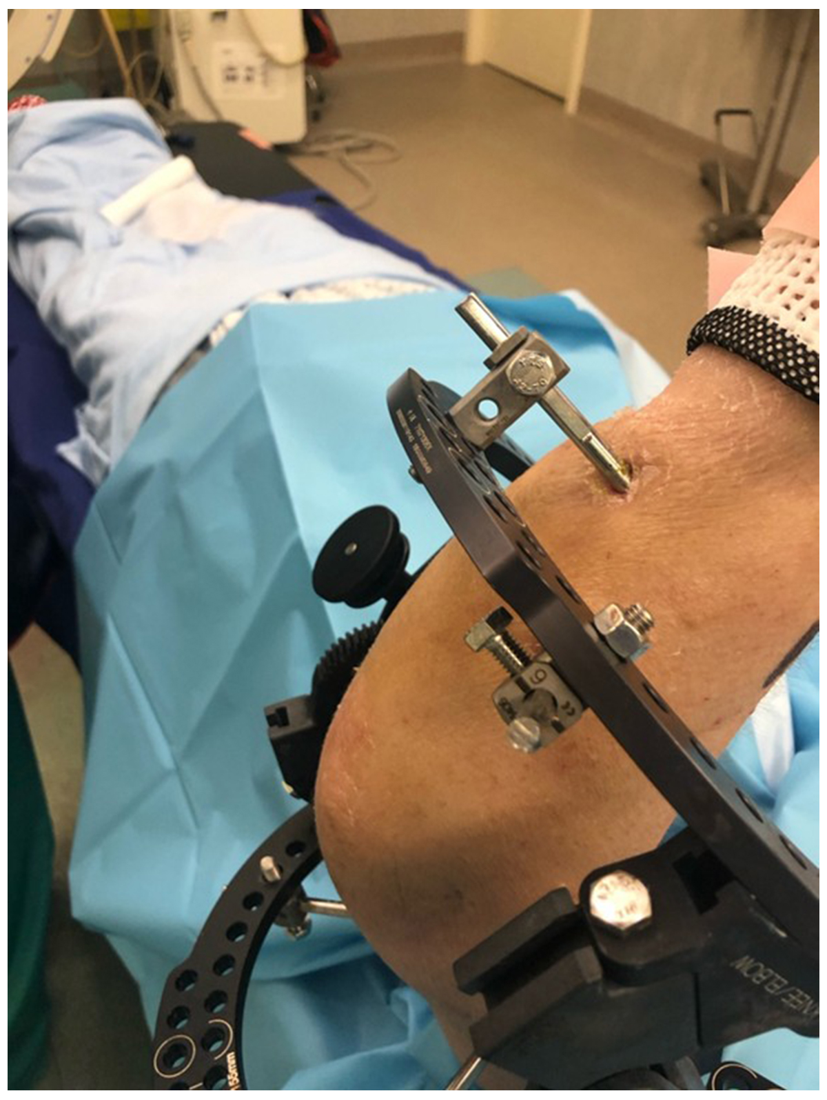
The COMPASS Universal Hinge is easiest to apply with the patient positioned lateral and the arm over a bar flexed to 90˚. This allows adequate access to the posterior surface of the elbow. Two 2/3 Rings should be used with the forearm Ring attached to the ulna with small diameter half-pins (3mm or 4mm), and the humeral Ring with standard size half pins (5mm or 6mm). There is no indication for Wires in this application as they do not provide enough stability to maintain the joint position.
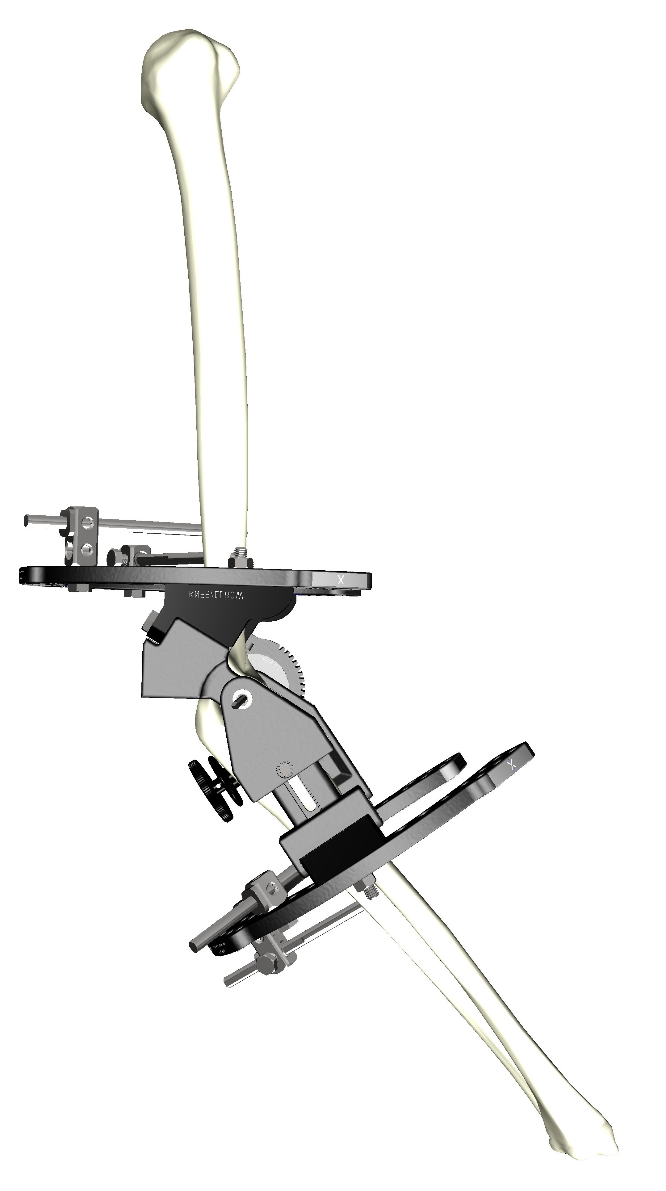
Establishing the Centre of Rotation of Elbow (CORE)
Initially the centre of rotation should be identified on the lateral view and a Smooth Wire.
The CORE Wire should be positioned through a mini incision on the medial side, given the proximity to the ulnar nerve.
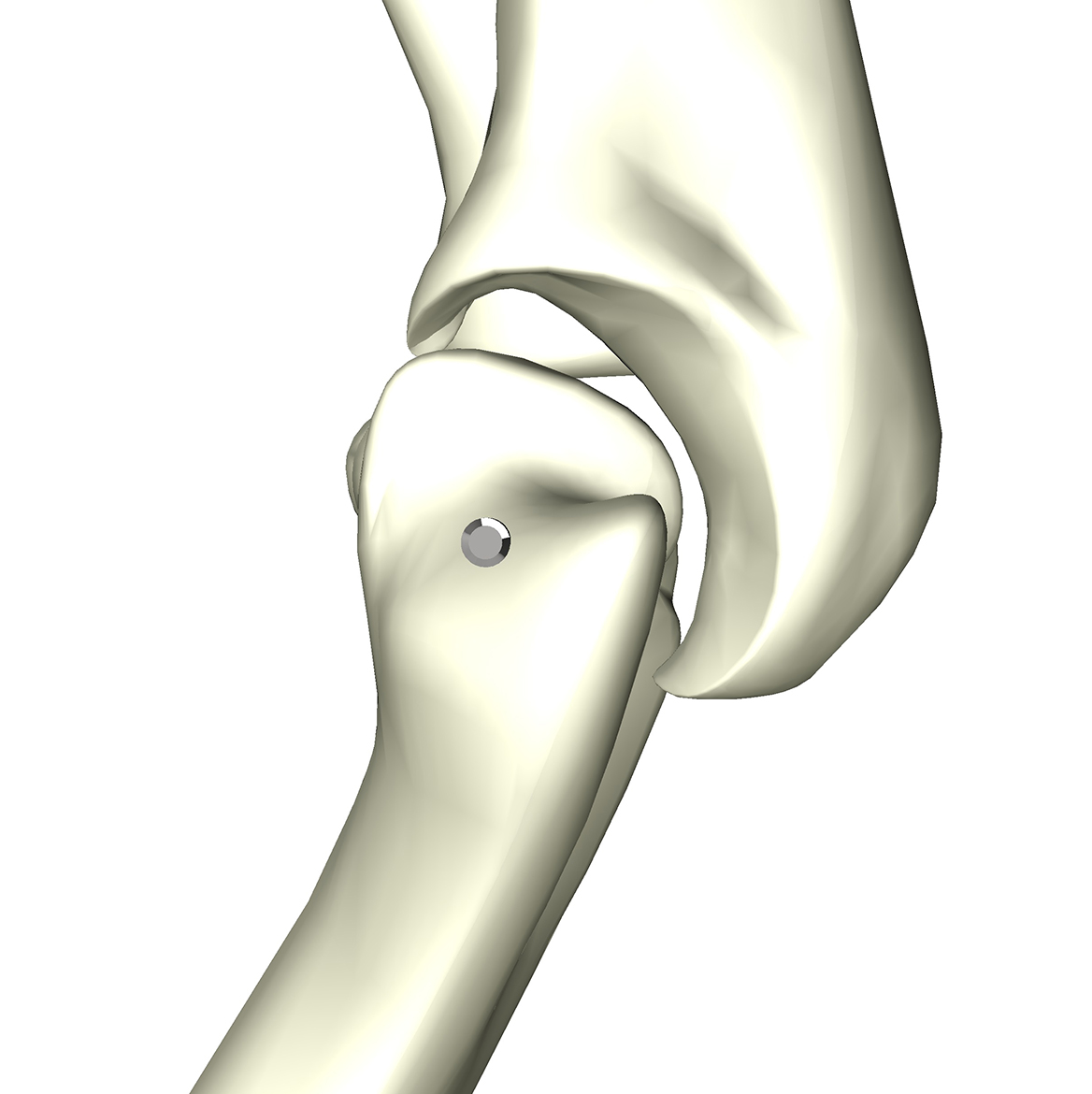
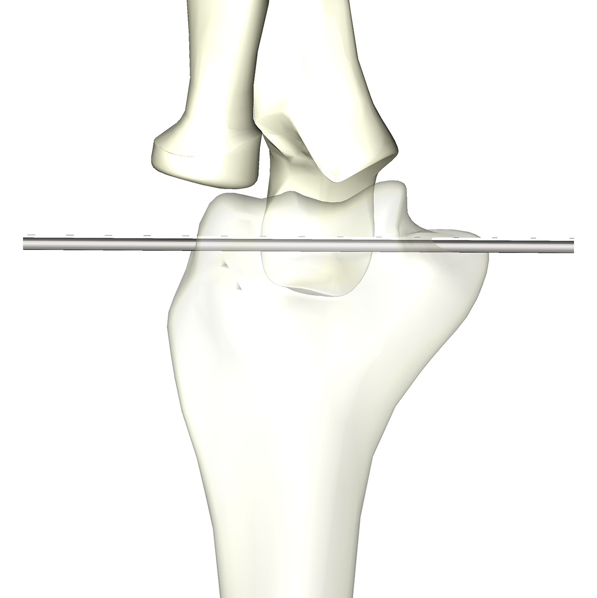
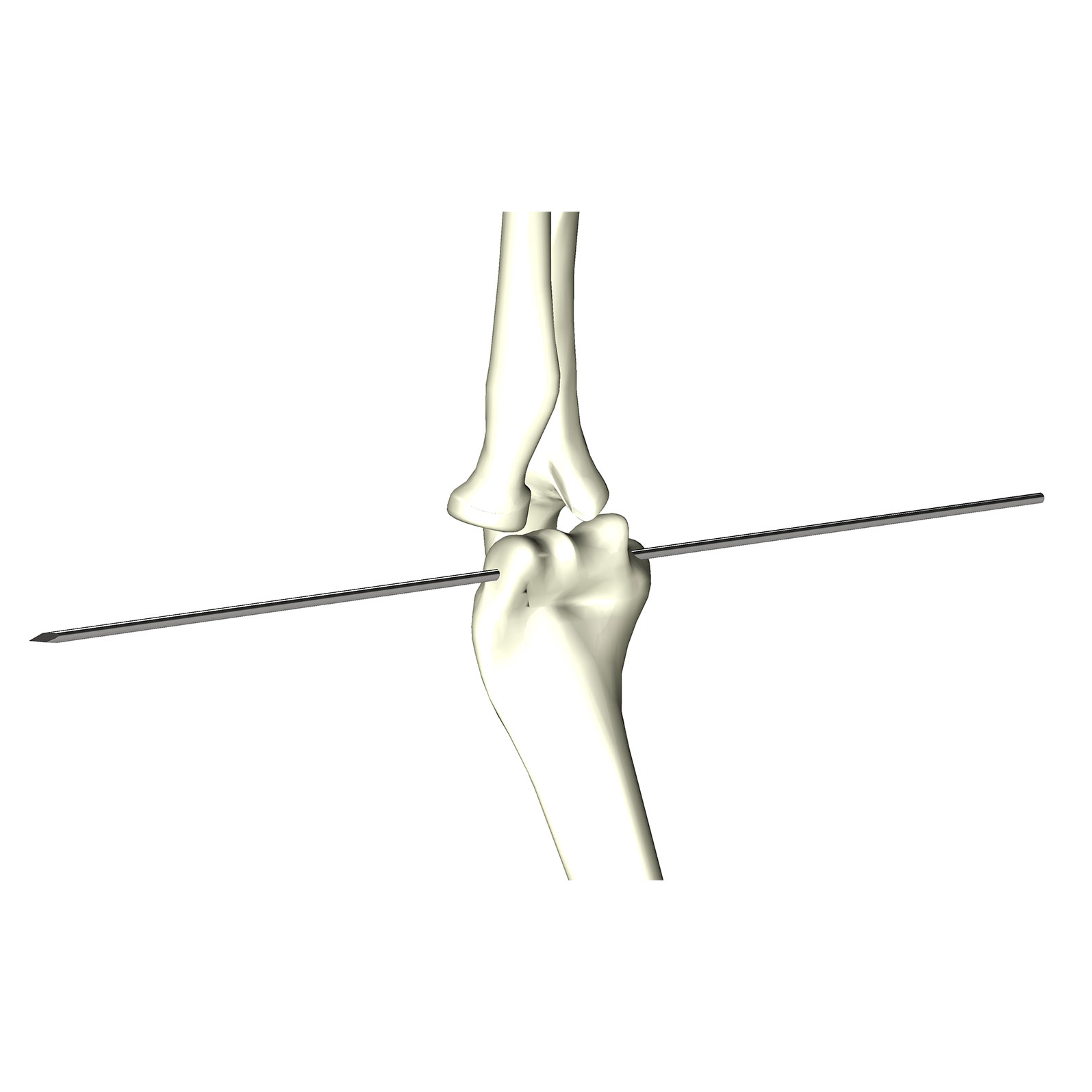
The most common indication here is the multiple ligament injury. In this indication it is considerably easier to mount the proximal Ring to the humerus first, followed by the distal Ring on the forearm. Similar to the quadriceps positioning, two half pins positioned para-triceptal, taking care to avoid the radial nerve, provide excellent stability to the ring. A 2/3 Ring provides additional stability to a Half Ring and is preferred.
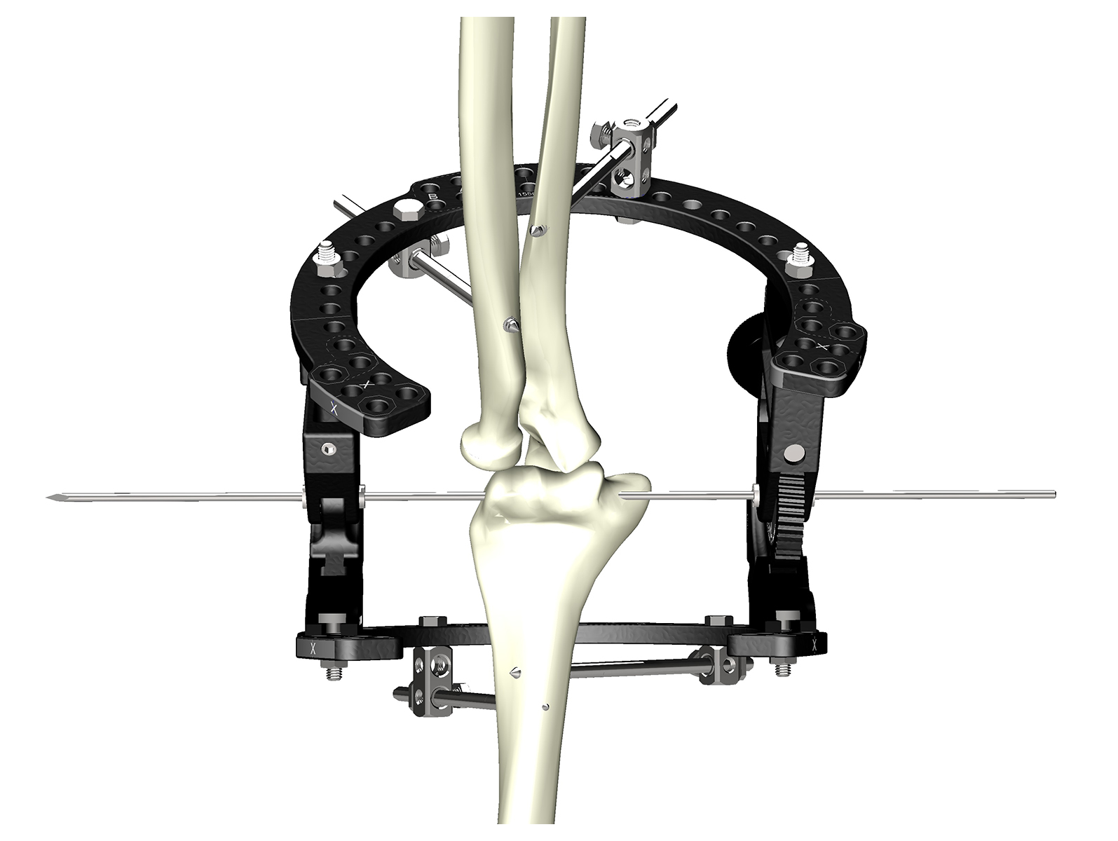
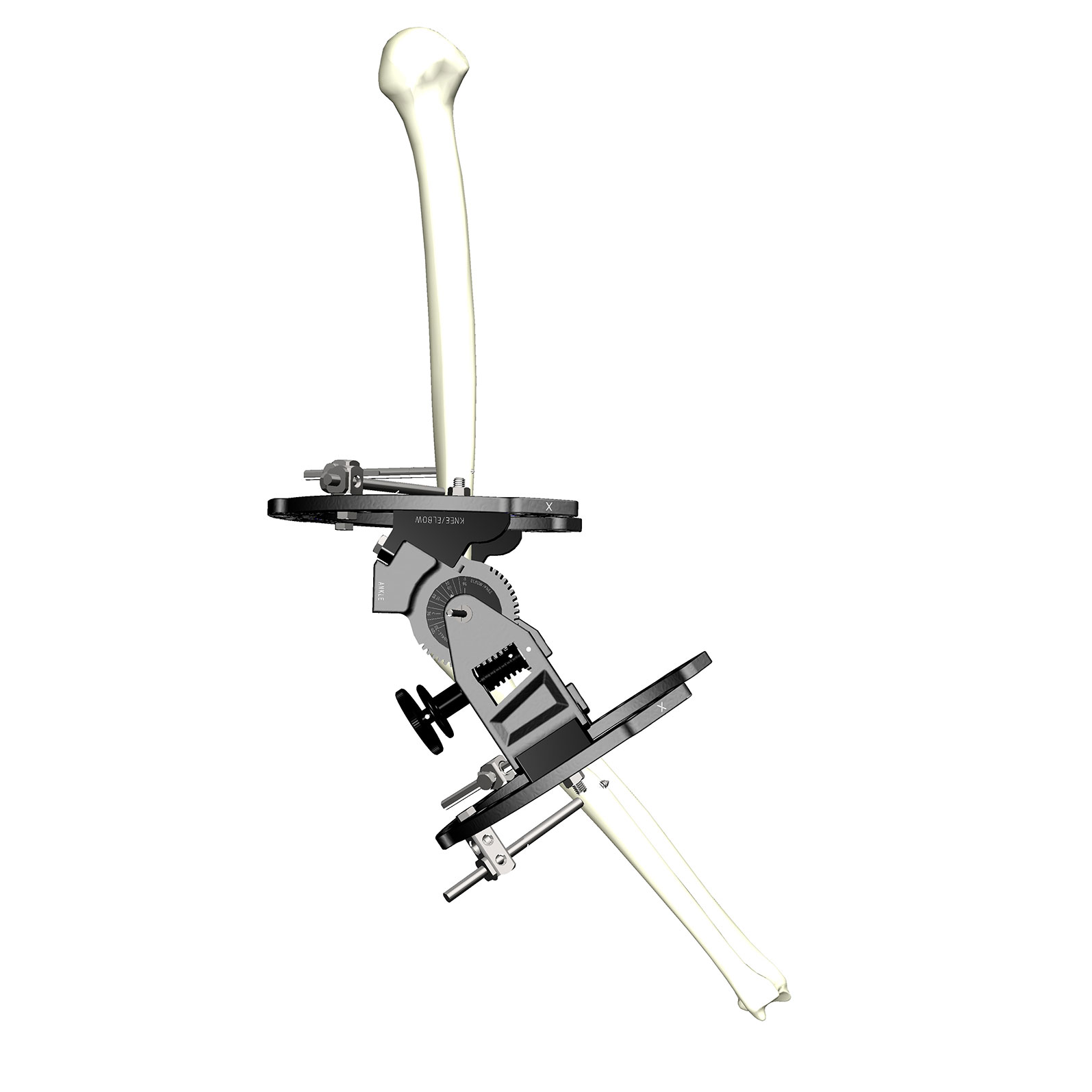
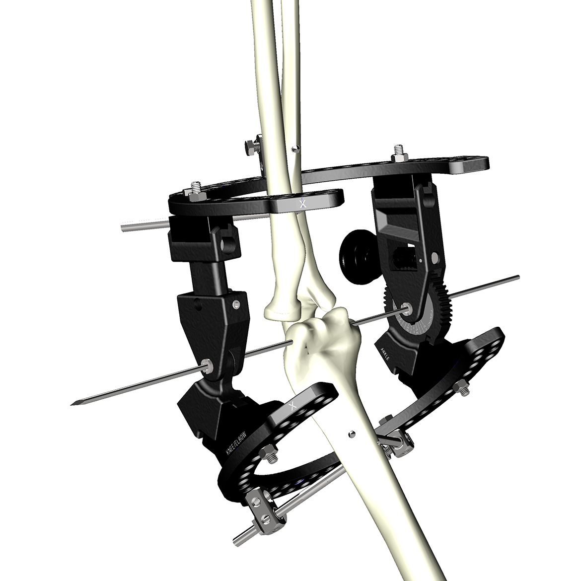
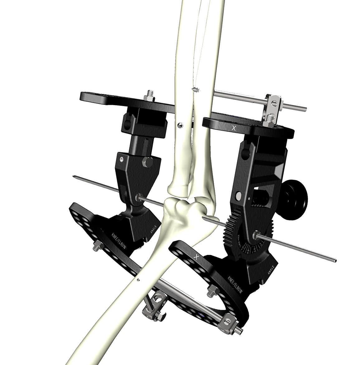
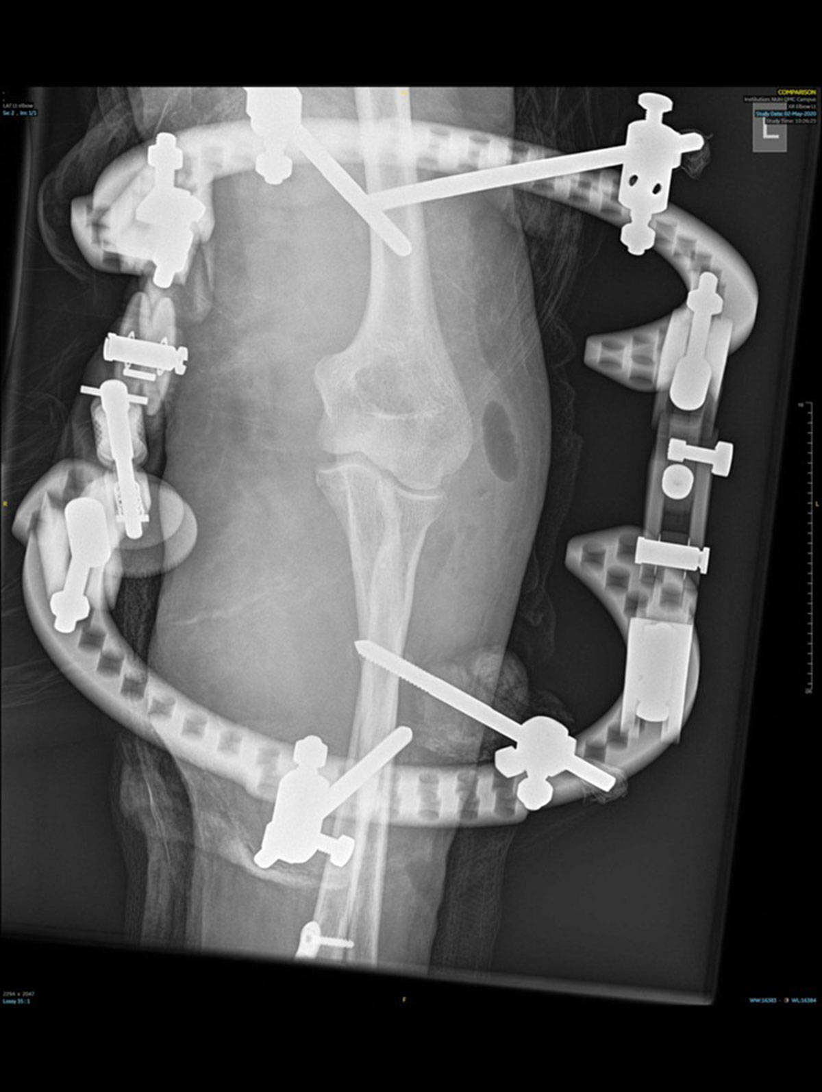
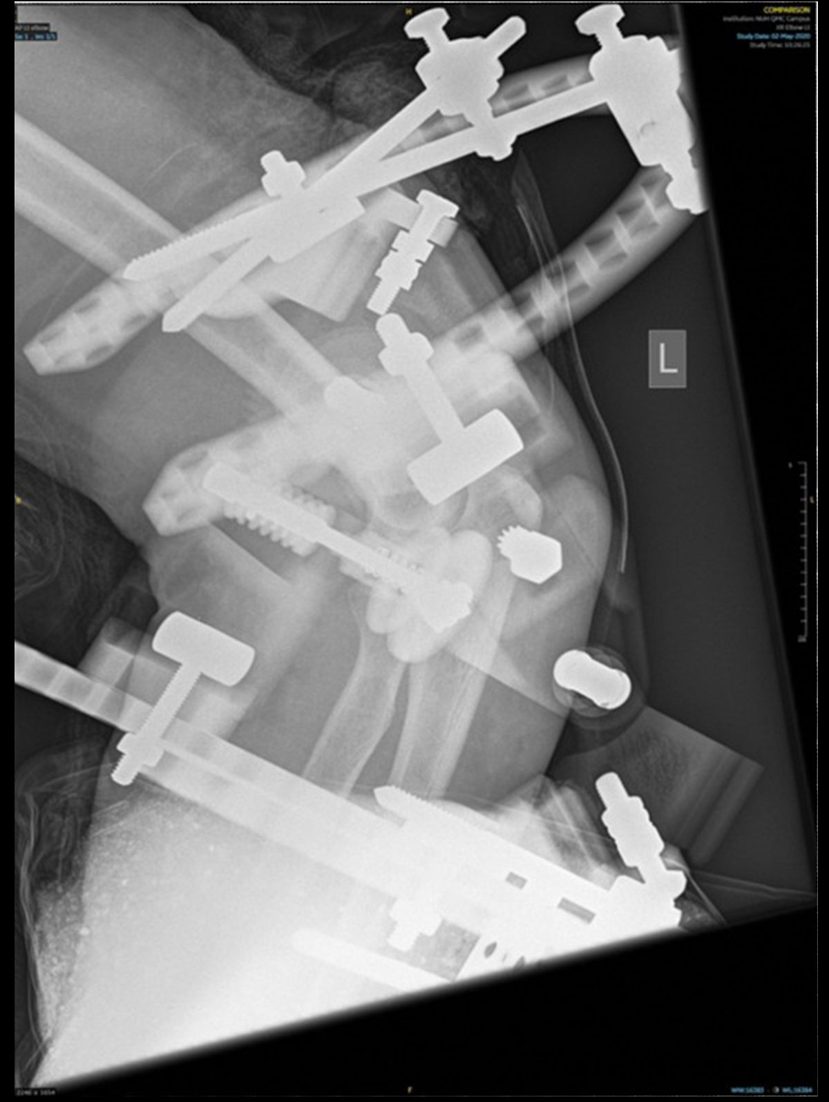
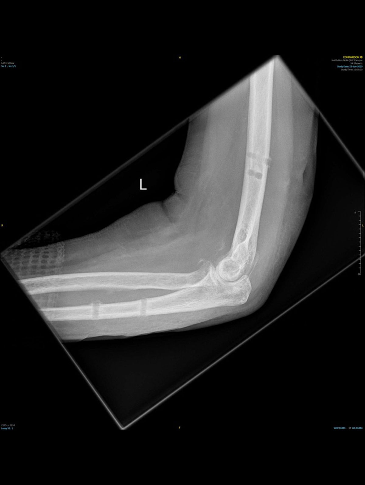
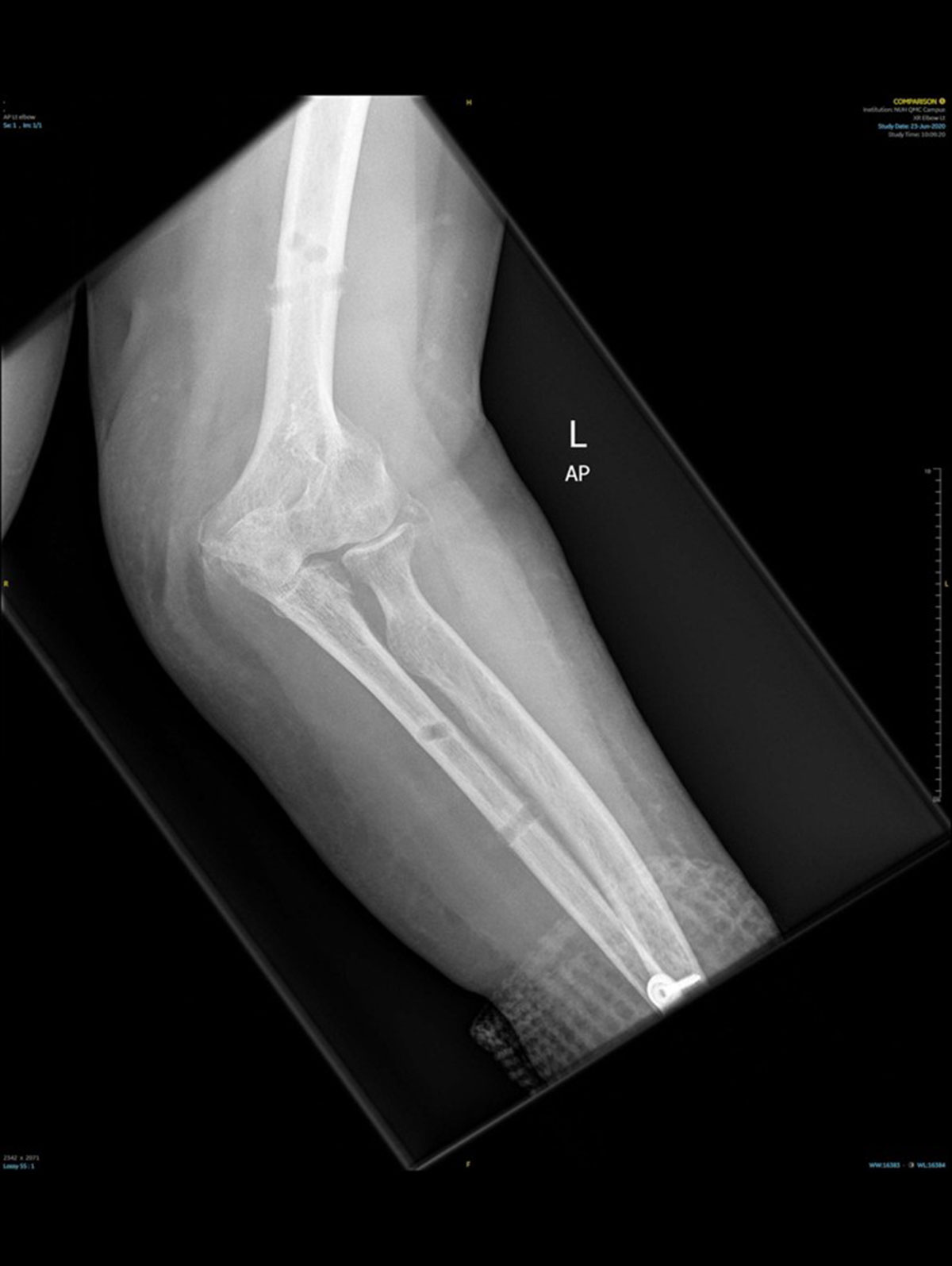
Careful positioning of the proximal Ring to maintain the axis will then allow secondary positioning of the forearm via the ulnar half pins. Optimal positioning of the pins are shown in the post-removal films below. Consideration should be given to protecting the pin sites post-frame removal as periprosthetic fracture in the ulna is a watch-out.
The distal 2/3 Ring is then built from the proximal Ring. The elbow can either be temporarily transfixed in joint with a K-wire to facilitate this – or when positioned lateral often the table bar helps maintain reduction. The pins are then carefully positioned into the ulna and the joint position checked.
Tip: It is extremely easy to pull the elbow out of joint at this point. Using the most proximal half pin first makes this less likely, as is using the Rancho Cubes with Posts as they have less ‘play’ in the Ring-Cube interface which serves to provide initial better stability.
Two half pins are sufficient to maintain stability and the elbow should be mobilised immediately. The ratcheted side of the COMPASS Universal Hinge can be adjusted to ensure carrying angle is optimal, and gear side should be positioned such that the gear is unlocked in the first instance.
Tip: When wishing to apply traction to a joint, position the COMPASS Universal Hinge as you would usually with the joint congruent. Then as a final step position washers between the proximal Ring and the COMPASS Universal Hinge. This serves to distalise the centre of rotation of the COMPASS Universal Hinge relative to the humerus and will distract the ulna throughout its flexion arc.
Case Example – Elbow
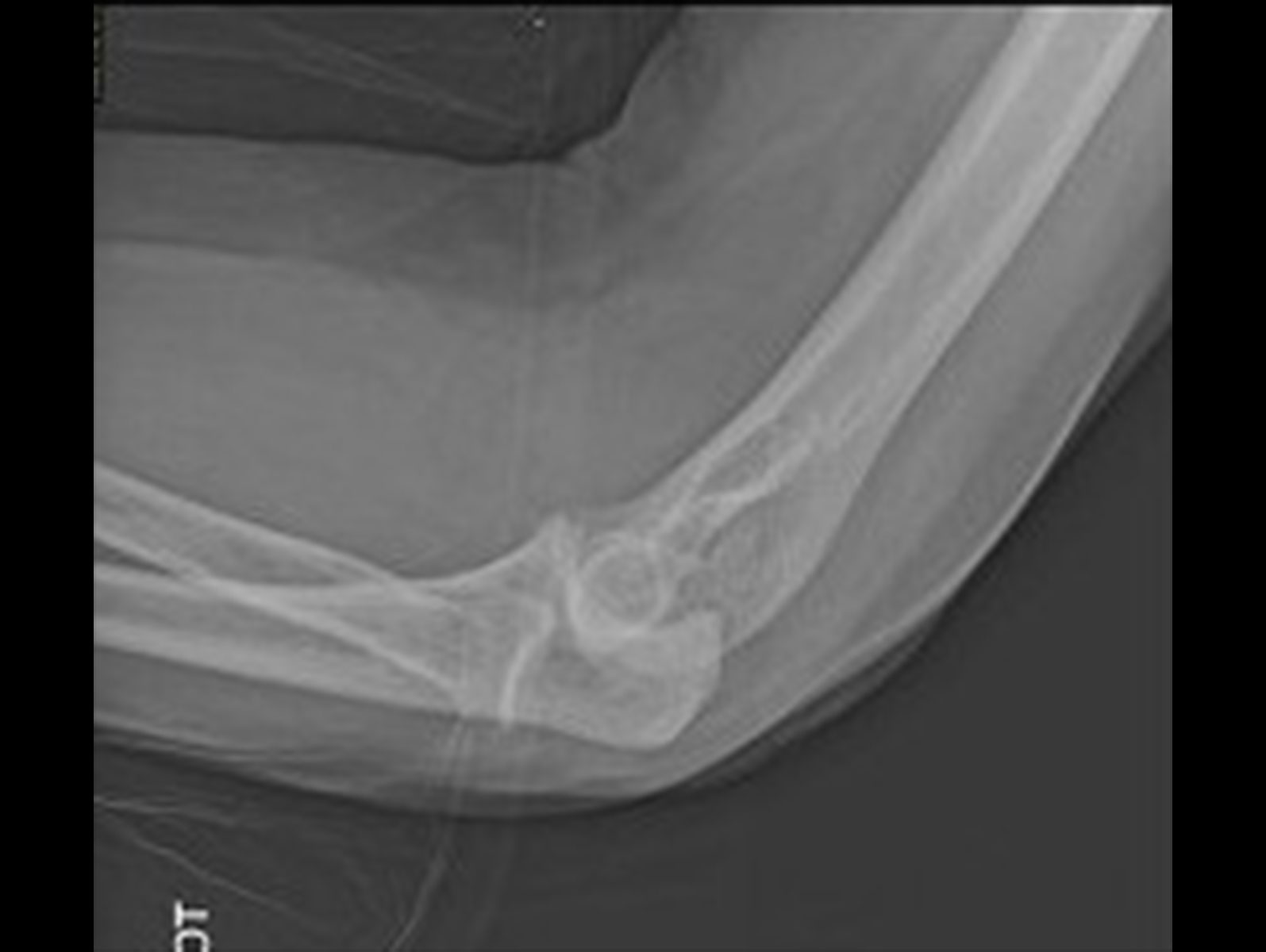
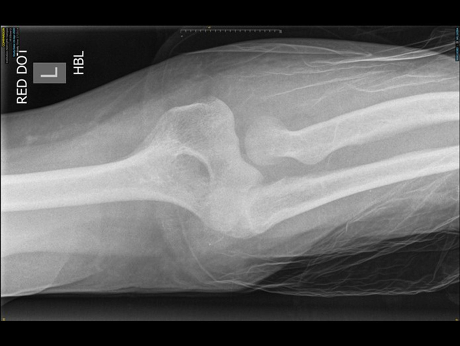
70 year old female
High energy fall resulting in dislocation of the elbow with disruption of interosseous membrane (Essex-Lopresti lesion).
References
- Sontich JK. Posttraumatic Taylor Spatial Frame deformity correction in adults. Operative Techniques in Orthopaedics. 2011;21:2:129-143. doi:10.1053/j.oto.2011.01.012.
- Henderson ER, Feldman DS, Lusk C, van Bosse HJ, Sala D, Kummer FJ. Conformational instability of the Taylor Spatial Frame: a case report and biomechanical study. J Pediatr Orthop. 2008;28(4):471-477. doi:10.1097/BPO.0b013e318173ecb1.