How and Why I Use Chronic Mode in TSF◇ Software
Christopher Iobst, MD, Nationwide Childrens Hospital, OH
The views and opinions expressed in this section are those of the surgeon.
Introduction
This section will explain the use of Chronic Mode for the purposes of pre-building the TSF before surgery. TSF software has two operating modes, Chronic and Total Residual. Total Residual is the most commonly used mode. It is a Rings-First method, designed for making adjustments to the frame after surgery. It is a useful tool because it does not require Rings to be parallel to one another or even orthogonal to the bone. It allows the surgeon to describe the frame to the software after it has been applied to the patient and to make iterative revisions to the program until the desired result is achieved.
In contrast, Chronic Mode is intended to be planned ahead of surgery. In this mode, the software starts with two non-parallel Rings orthogonal to their respective bone segments (Figure 1a). The adjustment of Struts during the correction results in a final construct with Rings parallel to one another (Figure 1b). It has been described as a “crooked frame on a crooked bone” ending up as a “neutral frame on a straight bone.”
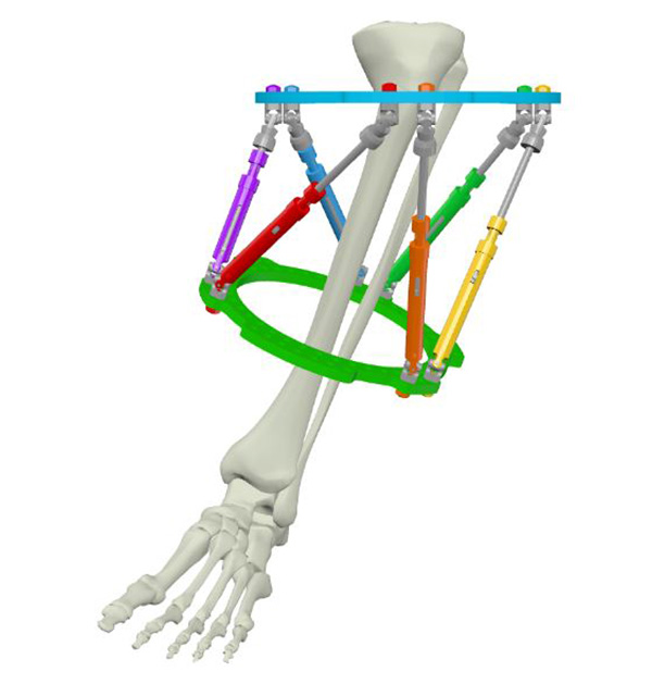
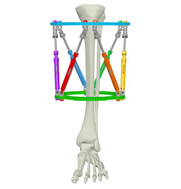
This technique is helpful both intuitively and visually as the patient and surgeon can watch the Rings gradually become parallel indicating the progression of the correction process. Chronic Mode pre-planning allows the surgeon to optimize the initial Strut settings thereby minimizing Strut change-outs. Perhaps most importantly, as the final frame is a neutral construct, the patient weight-bears during consolidation on a construct that is orthogonal to the mechanical axis.1
When to use Chronic Mode?
Chronic Mode is best utilized when planning an elective bone deformity correction (eg, malunion, Blount’s disease, etc.). With practice, it takes just a few minutes to design a frame that will match the pre-operative deformity. This initial investment in time will pay dividends in the operating room by simplifying and optimizing the frame application.
Chronic Mode requires pre-operative planning and stable alignment, and as such is difficult (but not impossible) to use for acute trauma. Chronic Mode is also not recommended when planning to correct a joint contracture that has a soft tissue release as part of the frame application surgery. Since the degree of joint contracture measured pre-operatively will change after the soft tissue procedure(s), a pre-built frame will no longer match the corrected limb deformity. Equinus contracture correction with concomitant Achilles tendon lengthening, for example, involve partial deformity correction at the time of surgery.
Why use Chronic Mode?
There are many benefits to pre-building the TSF◊ before surgery. First and foremost, it forces the surgeon to mentally work through the surgery before entering the operating room. By comprehensively analyzing all four dimensions of the deformity, templating the Ring sizes, and determining the desired rate of correction as a pre-operative virtual exercise, the actual surgery will be more efficient and have a better chance for a successful outcome.
Deformity surgeons are encouraged to think through each step of the surgery and write those steps down on paper. This document can be posted in the operating room on the day of surgery to enhance communication among the team as everyone can follow along together. It also helps keep the surgery on track and avoid skipping or missing any steps. Performing the surgery virtually in the pre-operative stage allows the surgeon to anticipate problems before they happen and make appropriate plans.
The second reason to pre-plan in Chronic Mode is the ability to design the cleanest possible Prescription for the patient. The Ring positions can be virtually moved closer together or farther apart in the software until a Prescription is created that has the minimum number of Strut changes possible. In many cases, the distance between the Rings can be manipulated to a sweet spot where no Strut changes are necessary. Since performing Strut changes can be a time-consuming process in clinic that may also cause anxiety for the patient, creating a Prescription that has the fewest possible change-outs is ideal. In addition, by eliminating the need for extra Struts, added cost can be avoided.
The third reason for pre-building with Chronic Mode is the opportunity to have the actual frame in your hands to evaluate. The size and orientation of the construct can be checked on the patient in the clinic or held up to the radiograph for comparison. This visual analysis of the frame also allows the surgeon to double check that there were not any errors in data input into the software which may have produced an unexpected frame design. Having the frame pre-built also saves time in the operating room. Since the frame already matches the limb deformity, once the frame is positioned on the limb in its desired location, the surgeon only needs to fix it in place. This eliminates a lot of time spent thinking through the position of the individual Rings and where fixation elements need to be applied. It allows the ideal position of each fixation element to be chosen since the Struts are already connected to the Rings and, therefore, their path is known and visualized. This prevents any fixation element from being inadvertently placed where Strut traffic will cause a problem.
Setting up a Chronic Mode case
Chronic Mode planning requires the same information as the Total Residual Mode:
- Hardware used
- Deformity parameters
- Mounting parameters
However, there are two additional pieces of information to be gathered before surgery when creating a Chronic Mode plan:
- The patient’s appropriate Ring sizes
- Rotational deformity assessment
Chronic Mode summary of workflow
Assessment of the patient and Software inputs often run concurrently as part of the planning. The steps are listed here as a summary, and are not necessarily sequential.
In the clinic
- Hardware – decide Rings size and Strut family
- Define Neutral frame height or Neutral Strut length
- Perform deformity analysis on AP and Lateral radiographs taken
orthogonal to the reference segment
Software
planning
- Create a new Chronic Mode case in SMART TSF◊ Software and enter the data points listed in 1- 3
- Estimate mounting of Reference Ring
- Adjust Neutral frame parameters to optimize Strut change-outs
Surgery
- Surgery – apply a pre-built TSF
- Obtain post-op orthogonal AP and lateral radiographs
Post-op
- Perform a New Total Residual on Day One of the Chronic Mode Prescription
- Generate a Prescription for the patient
1. Choose hardware
Measure the patient in the clinic for Ring size. Commercially made templates or old Rings from previous cases can be used to assess the limb circumference. The ideal Ring size should have one to two fingerbreadths of clearance circumferentially. While it is possible to measure the soft tissue shadow on a radiograph and make an estimate of Ring size, sizing actual Rings on the patient is more precise.
Choose the Strut family, according to surgeon preference.
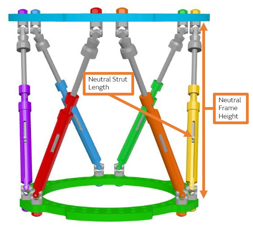
2. Define the Neutral Frame
The software needs to know the Neutral Frame Height or Neutral Strut Length (Figure 2). This represents the distance between the two Rings when the correction is complete, and the Rings are parallel. The final parallel Ring position can be described by either the actual distance measured between the two Rings (Neutral Frame Height) or by the ending number indicated on each strut (Neutral Strut Length). Because the Rings are parallel, by definition, all six Struts will finish at the exact same number.
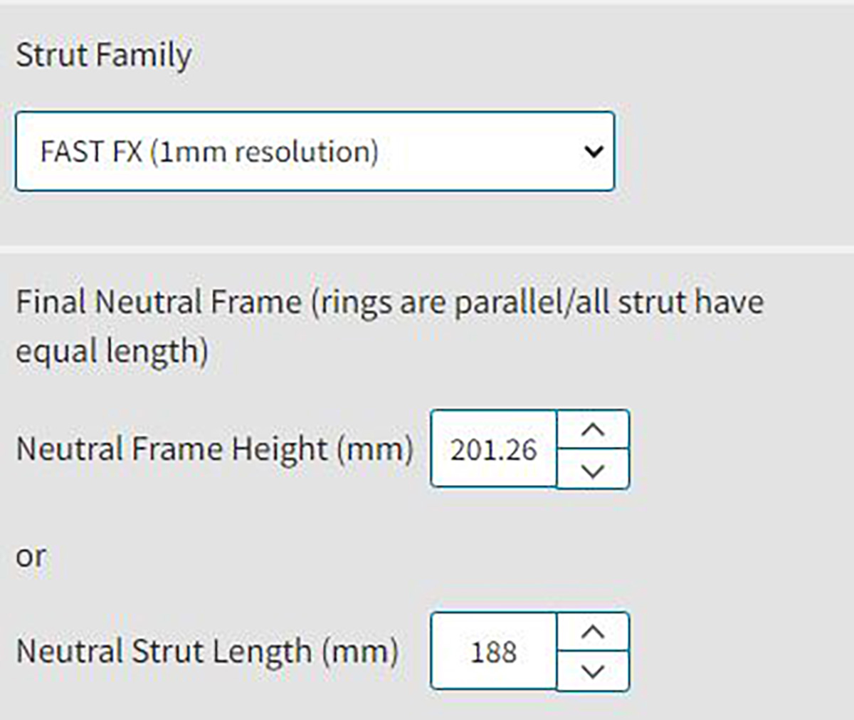
Although defining a neutral frame height is an option, it is easier to use the Neutral Strut Length method in Chronic Mode. As a starting point, choose the Neutral Strut Length to be the mid-point of the chosen Strut family. For example, choose 175mm for the Neutral Strut Length when using a medium FAST FX◊ Strut.
Osteotomies
The Chart below (Figure 3) helps define reasonable Ring / Strut combinations that result in a final frame with acceptable frame height and angles between Struts (Figure 4).
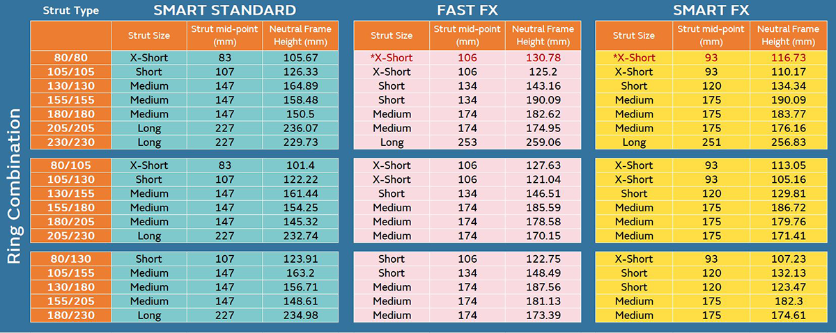
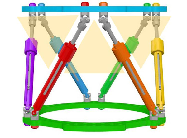
Final frame construct with reasonable Strut angles, Struts at partial excursion and Rings parallel to the mechanical axis. This is the frame the patient will walk on and heal in during the consolidation period.1 A Strut angle less than 30° is not recommended.2
The Neutral Strut Length can be tweaked, then construct viewed in Preview pane to visually assess the angles of Struts
When the neutral Strut length is entered the software will automatically calculate the neutral frame height. This can be used as a point of reference for the surgeon to know how far apart the Rings will be and whether or not this will fit appropriately on the intended limb segment.
It is important to understand that the initial projected Neutral Strut Length is just a starting point and can be modified after the rest of the Chronic Mode inputs are entered.
3. Deformity analysis
The surgeon will assess the deformity on AP and Lateral radiographs taken orthogonal to the patient’s anatomy. Deformity analysis can be performed using the digital tools within SMART TSF◊ (Figure 5), or outside the software and input manually (Figure 6).
A standard assessment of the patient’s limb rotation using the rotational profile prone examination (or with advanced imaging if desired) should be performed. Rotation is the only deformity parameter that cannot be obtained from standard radiographs.
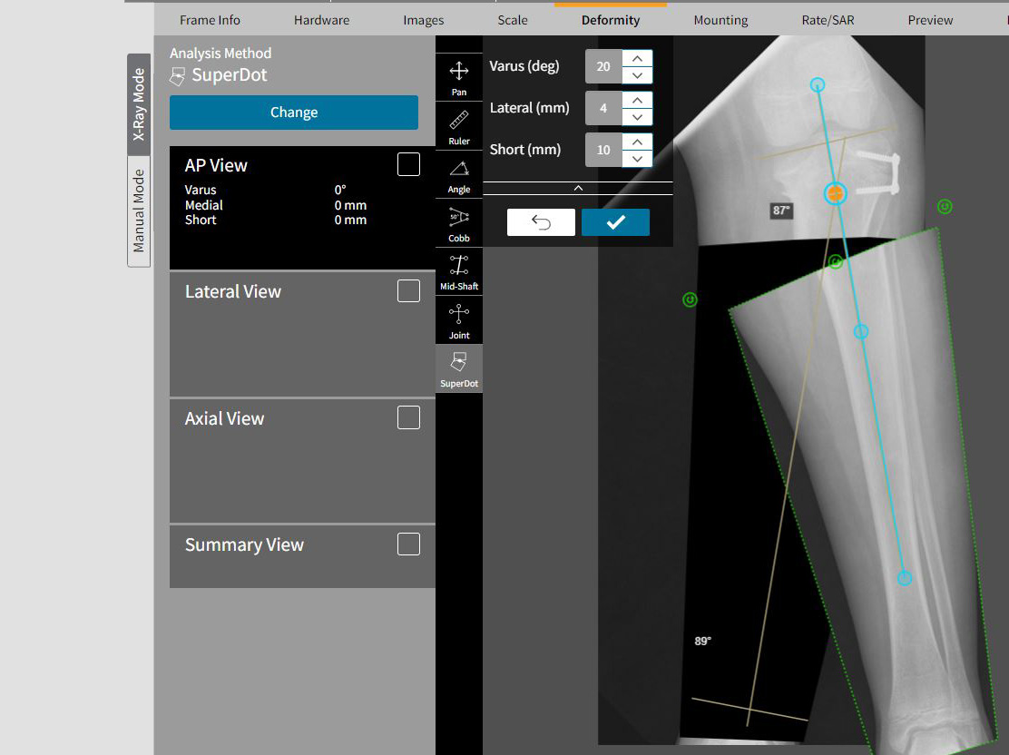
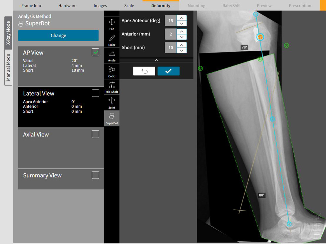
Figure 5
Pre-operative images uploaded for Deformity analysis in SMART TSF Software must have a calibration strategy that can be used to scale the X-rays on the tab “Scale.” Post-operative images can be scaled and calibrated using the SMART TSF Beacon. This example shows how SuperDot can be used to assess the deformity. The advantage of using SuperDot is that it will calculate obligate translation induced by correction in other planes
Figure 6
If deformity analysis is performed outside of SMART-TSF.com, then the magnitude and direction of each deformity parameter is input manually
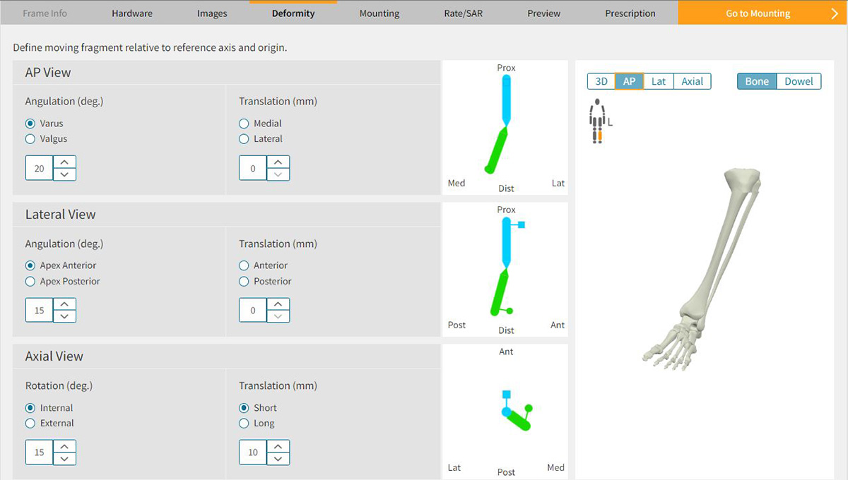
Regardless of which method is used to define the deformity, the rotation will need to be
entered manually based on the physical examination findings (Figure 7a). Therefore, it is
imperative for the surgeon to have documented this parameter pre-operatively in the clinic.
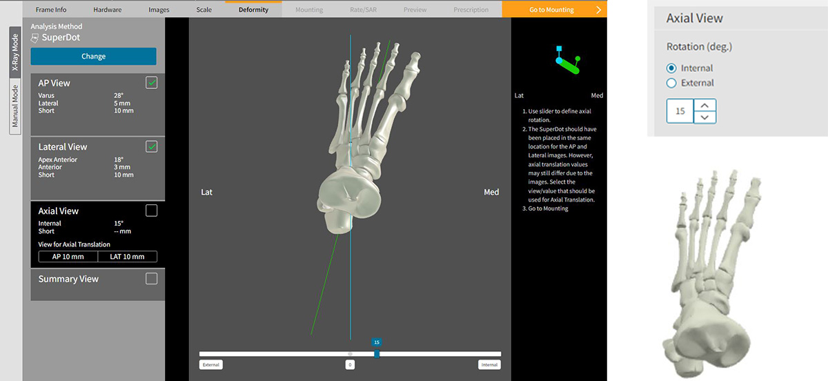
As the deformity parameters are entered, the three-dimensional image of the bone on the right-hand side of the screen should accurately represent the patient’s real deformity (Figure 7b). Use this as a double check that the information entered to the deformity parameters is correct (i.e. varus wasn’t inadvertently clicked when the patient has valgus).
It is important to note that the over/under correction tab is not active with Chronic Mode. Because the over/under correcting function designs a final frame with Rings that are not parallel, this would violate Chronic Mode’s directive to finish the correction program with two parallel Rings.

4. Create a Frame in SMART TSF◊ Software
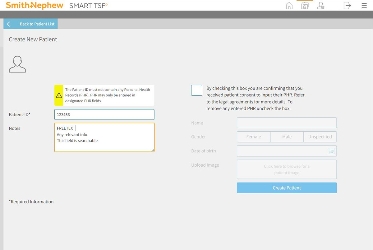
To begin the Chronic Mode process, the surgeon first logs in to the SMART TSF software to Create a New Patient (Figure 8a)
A patient ID must be entered. Any additional information is optional.
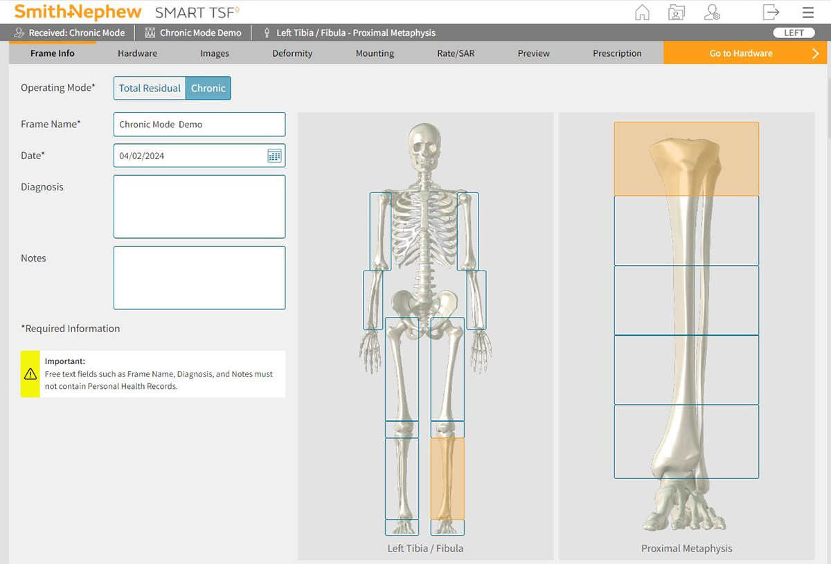
On the “Patient Sheet” the surgeon selects “Create New Frame.” This is where the choice of operating modes is offered. Choose Chronic to indicate that you will be pre-building the frame. Insert the mandatory information on this page (frame name and date) and then select the appropriate anatomy. (Figure 8b)
“Start Program” will direct the surgeon to the Essential Hardware page. (Figure 8c)
Enter the Ring size and type as defined in the clinic assessment
Enter either the Neutral Frame Height or Neutral Strut Length, as defined in clinic assessment
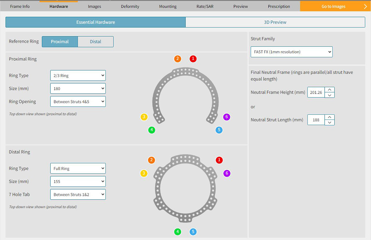
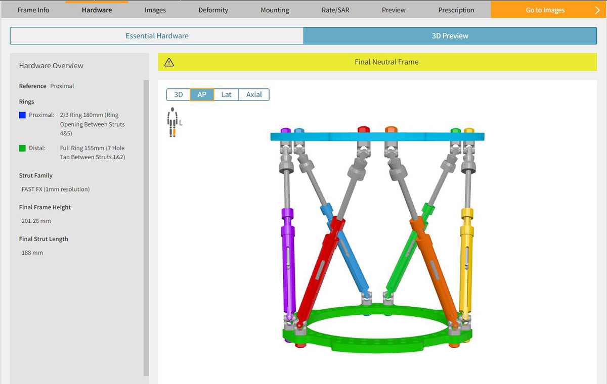
The 3D preview in SMART TSF◊ shows a neutral frame with the defined Ring sizes and types oriented parallel to one another, six Struts of equal length and Strut angles greater than 30˚. (Figure 8d)
5. Estimate Mounting of Reference Ring
Until now, every data input in the software has been a measurable, known entity and should be accurate (within the limits of human error).
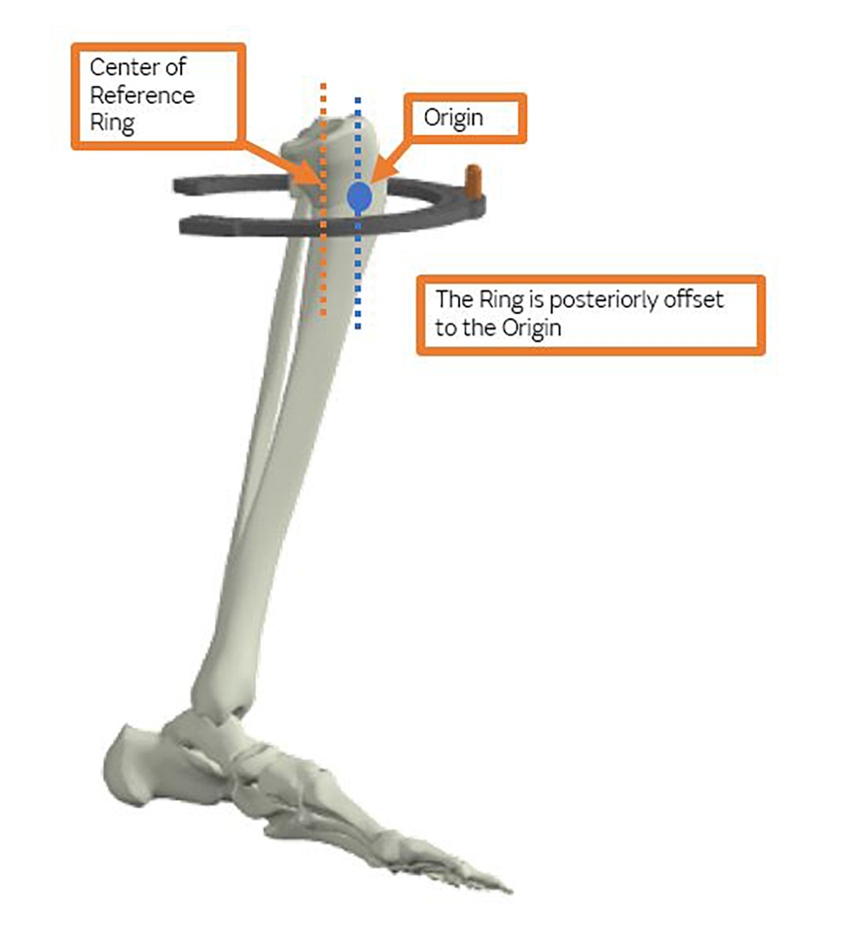
On the Mounting tab (Figure 9), however, the surgeon must provide an estimation of where the center of the Reference Ring is going to be located relative to the apex of the deformity (origin). In other words, this is the one element of the Chronic Mode that requires an estimation prior to performing the surgery. With practice, the accuracy of the guesses can be improved and often will be nearly perfect.
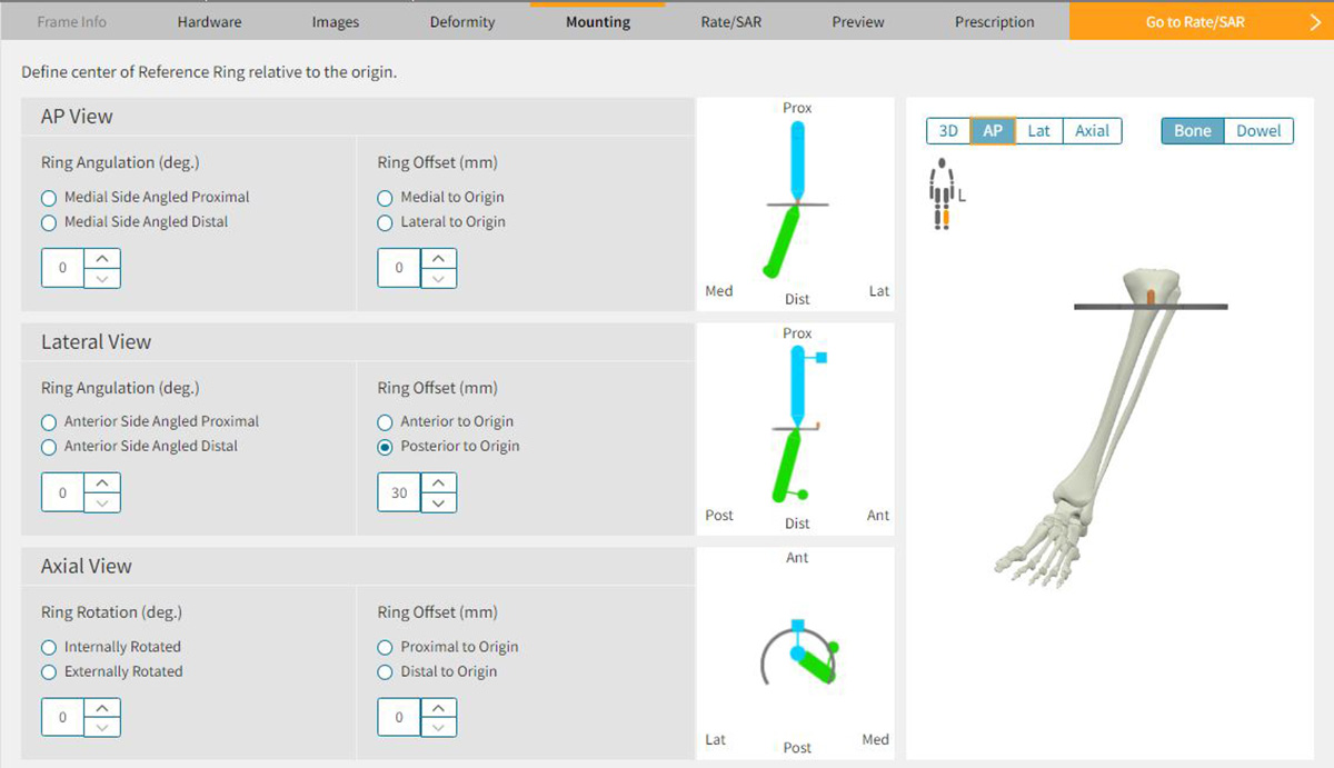
Mounting Parameters in SMART TSF◊ Software
Of the four required dimensions (axial, rotation, coronal and sagittal planes), the rotation and coronal planes are easily and quickly calculated for most tibial applications. These two measurements can be controlled by the surgeon with meticulous technique in the operating room. By mounting the frame with the Master Tab directly anterior over the crest of the tibia, the rotation plane will measure zero. Similarly, if the Master Tab is centered over the tibia, the medial/lateral component will also measure zero. A short Threaded Rod inserted into the central inner hole of the Master Tab will provide a visual cue of the Ring center position and make it easier for the surgeon to mount the Ring in the desired position with C-arm guidance (Figure 10). The proximal/distal measurement can be determined on the pre-operative radiographs.
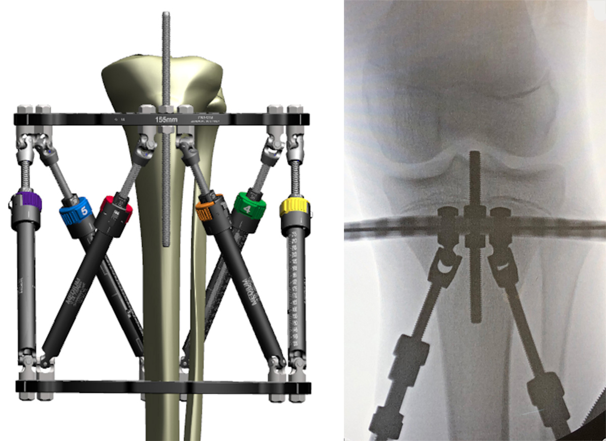
Use a Threaded Rod to assess Ring offset
under X-ray visualization
Once the surgeon determines the origin (apex of the deformity), the distance from this point to the anticipated level of attachment for the Reference Ring can be measured. For deformities where the apex is at the level of the physis (i.e. Blount’s Disease) the Ring can be mounted on top of a Wire inserted just below the physis. This places the Ring at the level of the apex making the proximal/distal offset zero.
The final component is the location of the center of the Ring relative to the origin in the sagittal plane. For most proximal tibial applications, the center of the Ring is located 25-40mm posterior depending on the size of the patient (Figure 11). As the deformity apex moves into the tibial diaphysis or distal tibia, the posterior distance decreases and often becomes close to zero.
Definitive Mounting Parameters will be assessed again later on post-operative radiographs and replace the estimated inputs during planning.
6. Adjust Neutral frame parameters to optimize Strut change-outs
At this point, the surgeon can advance to the next screen (rate/SAR) where the desired rate of correction can be chosen. This screen will reveal the number of Strut change-outs that will be necessary during correction (Figure 12a).

It is at this point that the surgeon can manipulate the Neutral Strut Length settings on the Hardware tab to create the optimal plan with the least number of Strut changes.
If one or two Struts are predicted to require a change but are only a few increments out of range of the next size, the Neutral Strut Length can be adjusted (up or down) to accommodate the necessary change.
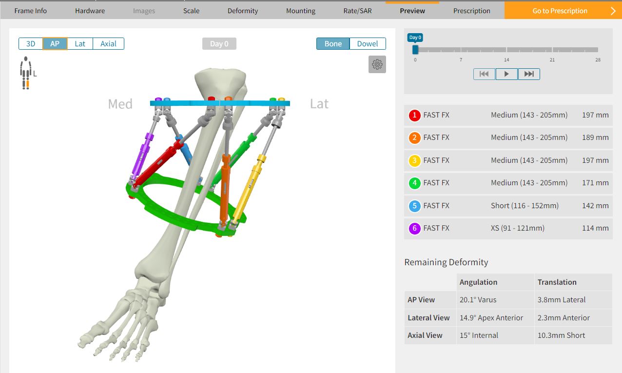
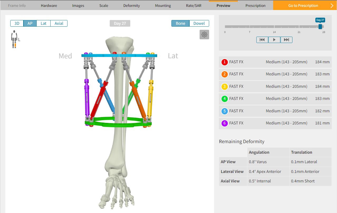
For example, in a right tibia varus limb deformity, the software may determine that Struts 2 and 3 need to start at length 135mm when the Neutral Strut Length was set at 175mm. This mandates two Short Struts changing to Mediums. The shortest excursion on Medium is 143mm, 8mm away from 135mm. By changing the neutral Strut length to 183mm (175+8) the distance between the Rings increases slightly. Struts 2 and 3 will now fit within the excursion of the Medium Struts and two strut change-outs have been eliminated (Figure 12b).

Adjusting the Neutral Strut Lengths can be done repeatedly until the optimal Strut length is identified that creates a program with the least number of Strut changes. Often, the Neutral Strut Length can be manipulated to eliminate all Strut changes from the Prescription. When adjusting the Neutral Strut length, remember that pulling some Struts into range may also push some Struts out of range. There needs to be a balancing act to find the optimum distance between the Rings for all six Struts.
The other important point is that the surgeon needs to verify that the optimal distance between the Rings will still allow the frame construct to fit appropriately on the patient. In other words, don’t increase the distance (or decrease the distance) to the point where the frame no longer anatomically makes sense for your patient, or the Struts assume an unreasonable angle.
On the Preview Tab (Figure 13a and 13b) the graphic should illustrate the frame in the desired orientation and location matching the deformity in the bone/limb. This image can be clicked and moved around to evaluate it in all planes. To the right of the screen, the six Struts are listed by type and setting. The initial settings are calculated creating a “crooked” frame that matches the limb deformity. Play the correction to see how the Struts change. If this primary plan indicates that no Strut changes are necessary then you have finished your Chronic Mode pre-build!
7. Surgery – apply a pre-built TSF
Referring to the Initial Strut Settings in the Chronic Mode plan, the frame can be assembled and sterilized ahead of surgery. Alternatively, the Rings and Struts can be assembled in the sterile field, at time of surgery. The TSF is attached to the limb using standard protocol described in other chapters. Refer to Section 5 Mounting Parameters to re-visit intra-operative tips for accurate mounting. The osteotomy is performed.
8. Obtain post-op orthogonal AP and Lateral radiographs
Post-operative radiographs should focus on capturing the anatomy – ideally the osteotomy and reference joints. The Beacon will serve to scale and calibrate the X-rays images and automate the Mounting Parameters.
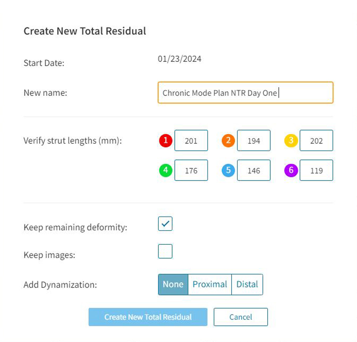
9. Perform a NEW TOTAL RESIDUAL on day one of the Chronic Mode Prescription
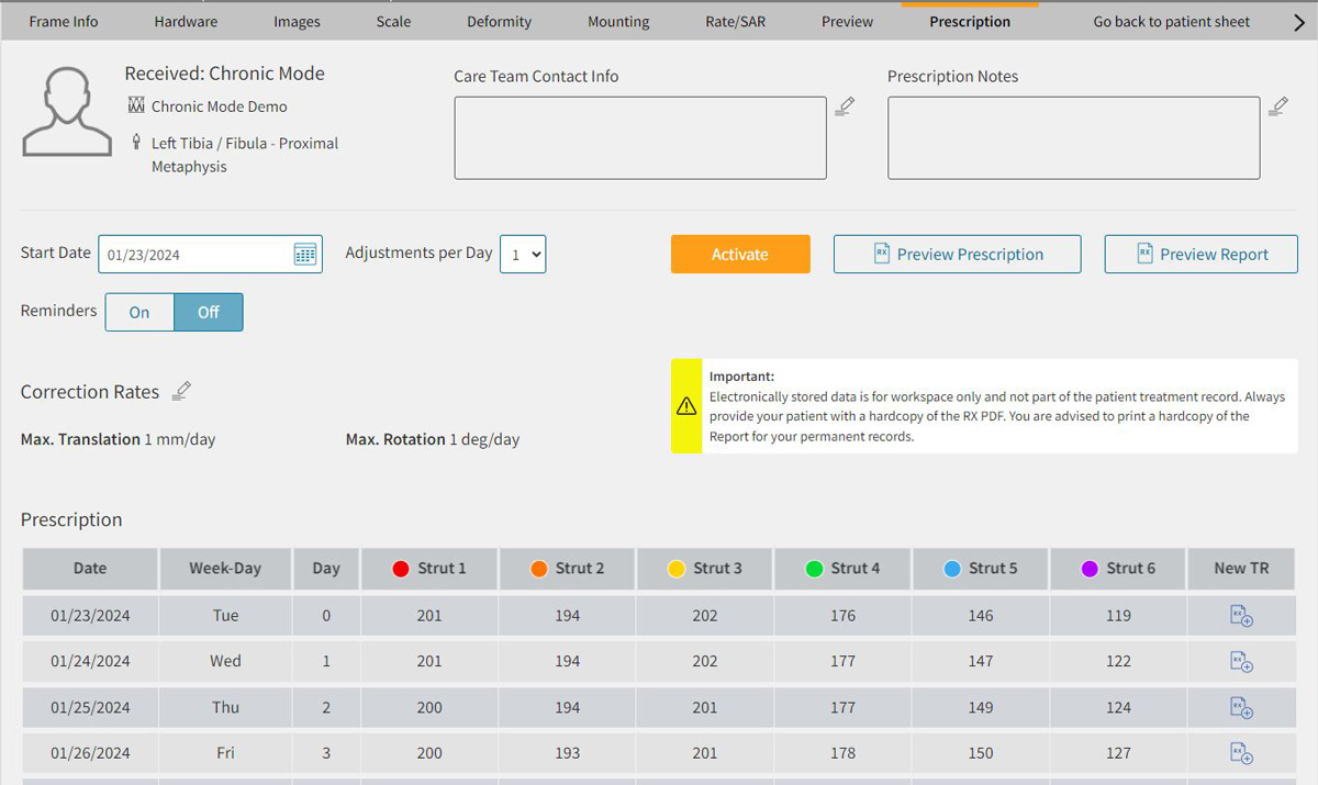
- Converting a Chronic Mode Plan to a Total Residual Program on Day One allows any deviation from the plan to be captured efficiently.
- In the software, navigate to the Chronic Mode plan that has been created and proceed to the Prescription tab. On Day One, select NTR (Figure 14).
- Navigate through each tab to check and confirm the inputs.
- Post-op X-ray images can be uploaded to drive accurate digital analysis of the Mounting Parameters.
- The Preview is the final visual check that the Deformity, Hardware and Mounting Parameters align to the clinical presentation.
10. Activate the Prescription
Once satisfied that all parameters reflect the patient’s deformity, initial hardware settings and correction desired, the program can be activated and Prescription generated for the patient.
References
- Sontich JK. Posttraumatic Taylor Spatial Frame deformity correction in adults. Operative Techniques in Orthopaedics. 2011;21(2):129-143.
- Henderson ER, Feldman DS, Lusk C, van Bosse HJ, Sala D, Kummer FJ. Conformational instability of the taylor spatial frame: a case report and biomechanical study. J Pediatr Orthop. 2008;28(4):471-477.
